

4 Common Styles Of Ball Locking Pins And Their Uses
Views: 0 Author: Site Editor Publish Time: 2026-07-18 Origin: Site


In manufacturing, aerospace, and heavy machinery, rapid changeovers and structural safety constantly intersect. Quick-release fastening systems serve as the critical bridge connecting these operational demands. Every standard Ball Lock Pin shares a similar mechanical push-button detent function. However, treating them as interchangeable commodities remains a major engineering mistake. Specifying the wrong handle style or material compromises basic ergonomics. It creates severe clearance hazards and leads directly to premature mechanical failure. You cannot afford arbitrary hardware selection when handling heavy dynamic loads. This article provides an evidence-based framework for engineers and procurement managers. We will help you evaluate, select, and specify the correct pin style based strictly on your operational realities. You will learn how to match handle designs to spatial constraints. We will explore how to evaluate material shear strengths safely. Finally, you will navigate sizing precision to ensure lasting, secure performance across your assemblies.
Key Takeaways
Style Dictates Application: T-handles prioritize leverage and gloved-hand operation, while Button and L-handles solve strict clearance limitations.
Load Constraints: Ball lock pins are engineered primarily for shear loads, not tensile loads; specifying the wrong material (e.g., 300 series vs. 17-4 PH stainless) dictates failure thresholds.
Sizing Precision: Accurate grip length and strict hole tolerance (typically +0.001" to +0.002") are non-negotiable for safe implementation.
Compliance & Environment: Environmental realities (vibration, debris, marine environments) must drive the final shortlisting process.
The 4 Common Styles Of Ball Lock Pins (And When To Use Them)
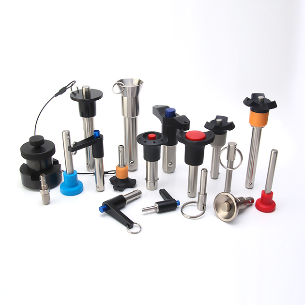
Understanding the handle design is your first critical step. Handle styles directly dictate how operators interact during high-pressure changeovers. We classify them into four primary categories. Each solves a specific ergonomic or spatial problem.
T-Handle Ball Lock Pins
The T-handle features a wide, perpendicular grip. It allows operators to wrap their fingers fully around the top. We recommend this robust design for heavy-duty applications. Ground support equipment often relies on this style for rapid deployment. Environments requiring heavy work gloves demand this exact configuration. Workers cannot manipulate tiny buttons while wearing thick protective gear. Shipyard crews use them extensively for temporary scaffolding assembly. The massive grip prevents hand cramps during repetitive tasks.
This style is ideal for maximizing linear pull-force during extraction. The wide bar provides excellent leverage. You can pull the pin out easily even if alignment is slightly off. However, this design requires significant lateral clearance. The wide handle occupies substantial space around the insertion point. If adjoining components block the handle, operators cannot grip it effectively. Always check the surrounding clearance before specifying a T-handle.
L-Handle Ball Lock Pins
The L-handle provides an asymmetrical, right-angle grip. It looks like a single-sided lever attached to the main shank. We frequently see these in tight-tolerance assemblies and complex corner fixtures. This design allows the pin to rest flush against a mounting surface. Resting flush actively prevents unwanted rotation during machine operation.
It provides excellent leverage for extraction in confined spaces. You get adequate pulling power minus the full footprint of a T-handle. This makes it a smart compromise for dense machinery. Operators can grab the single protruding side easily. You avoid clearance clashes on the opposite side of the pin. We often specify L-handles near structural walls or tight brackets.
Button Handle Ball Lock Pins
Button handles feature a compact, low-profile knob. They offer the smallest possible footprint above the hole. You will find them heavily used in precision machinery. Fitness equipment manufacturers rely on them extensively for weight stack adjustments. Medical device manufacturers favor this clean aesthetic. Hospital beds and diagnostic carts utilize these low-profile fasteners. They prevent patients or medical staff from accidentally snagging their uniforms.
Engineers select this style when space is at an absolute premium. Protruding handles often pose a dangerous snagging hazard. A low-profile button eliminates the risk of catching loose clothing. It also prevents accidental bumping during operation. However, you sacrifice leverage. Operators must pinch the button tightly. It is much harder to pull out if the joint experiences high friction.
Ring Handle Ball Lock Pins
This design utilizes a minimalist pull-ring attached to the push-button mechanism. It represents the most basic approach to quick-release fastening. We suggest using them strictly for economical, light-duty applications. You will often spot them on lighting rigs and audio-visual equipment stands. Technicians appreciate the simple functionality. They work perfectly when holding lightweight aluminum telescoping poles together. They excel in assemblies requiring retention lanyards to prevent loss. You can easily loop a cable right through the ring.
This style is the least ergonomic option available. High-frequency extraction will fatigue the operator's fingers quickly. High-friction joints make pulling the ring incredibly painful. We reserve ring handles strictly for low-resistance removal. If the application involves heavy plates or alignment shifts, choose a different style.
Key Evaluation Criteria: Material Selection and Load Capacities
Selecting the correct handle only solves the ergonomic puzzle. You must evaluate the internal materials to guarantee structural safety. Failing to calculate load capacities correctly leads to catastrophic hardware failures.
Shear vs. Tensile Strength Realities
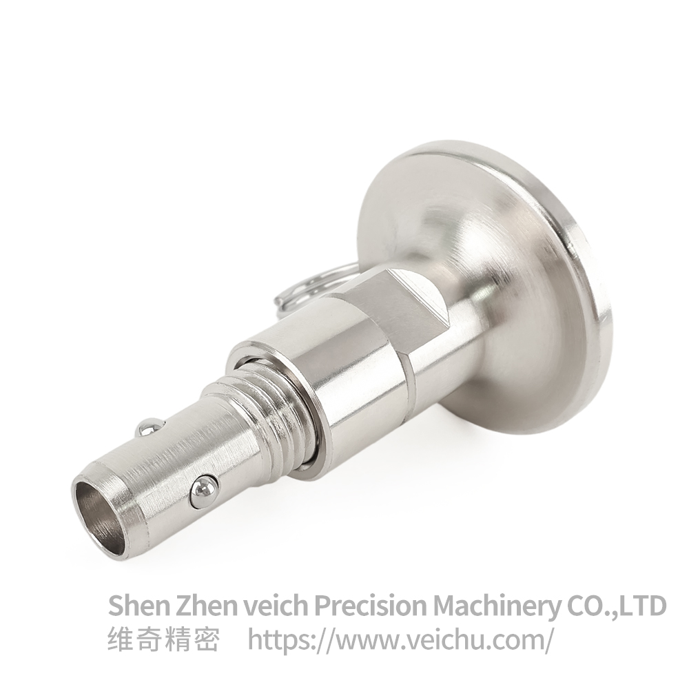
A Ball Lock Pin is engineered to resist lateral forces. We call these lateral forces shear loads. The solid metal shank bears the entire weight of the shifting plates. Imagine a heavy steel plate sliding downward. The pin acts as a solid bridge stopping the slide. This represents pure shear force.
Conversely, tensile forces pull directly outward along the pin axis. We must clarify a critical engineering reality. The internal detent balls cannot bear heavy pull-out loads. They are designed solely for alignment and retention against minor accidental bumps. If your assembly applies heavy active tensile loads, the detent balls will shear off. The internal spring mechanism will collapse. You must rely on bolted joints or threaded fasteners for high tensile requirements.
Material Shortlisting Framework
Your chosen alloy dictates the absolute failure threshold of the fastening system. We use a straightforward framework to shortlist materials based on environmental and structural demands.
Material Type | Primary Characteristics | Ideal Applications | Shear Capacity |
|---|---|---|---|
17-4 PH Stainless Steel | High yield strength, heat-treated durability | Aerospace components, heavy load-bearing fixtures | Maximum |
300 Series Stainless Steel | Superior rust and chemical resistance | Marine environments, food processing equipment | Moderate |
Alloy Steel (Zinc/Cadmium Plated) | High strength-to-cost ratio, surface protected | Standard industrial manufacturing, dry environments | High |
17-4 PH stainless steel delivers immense yield strength. It offers exceptional shear capacity for mission-critical joints. We specify it heavily for aerospace and heavy lifting fixtures. 300 series stainless steel provides superior corrosion resistance. It survives marine environments and chemical wash-downs perfectly. However, it possesses a lower overall shear strength compared to 17-4 PH. Alloy steel offers a high strength-to-cost ratio. Standard industrial environments use plated alloy steel extensively. Be careful, though. It remains vulnerable to long-term corrosion if the zinc or cadmium coatings degrade.
Compliance Standards
Mission-critical applications require strict regulatory adherence. You cannot guess the load limits of a random pin. Mentioning compliance is necessary for safety.
Common Best Practice: Always check NAS (National Aerospace Standards) certifications before installing pins in flight-critical hardware.
Common Best Practice: Verify MS (Military Standard) certifications for defense and heavy transport applications.
These standards guarantee the metallurgical consistency of the shank. They also verify the spring tension limits inside the push-button mechanism.
Implementation Risks: Sizing and Environmental Hazards
Even the strongest alloy will fail if installed incorrectly. Engineers frequently overlook spatial tolerances and environmental degradation during the final design phases.
The Grip Length Calculation
Measuring the active grip length accurately is a critical task. You must measure the exact distance from the bottom of the handle collar to the top edge of the detent ball. Over-sizing the grip length causes the clamped plates to rattle. This constant rattling induces fatigue across the joint over time.
Conversely, under-sizing the grip length creates an immediate safety hazard. The locking balls will remain trapped inside the hole. They cannot deploy fully to lock the pin in place. The pin will eventually vibrate out of the assembly. Always measure the total plate thickness precisely before specifying the grip length.
Hole Tolerance Requirements
We strongly warn against loose machining practices. Quick-release pins require exceptionally tight hole tolerances to function safely. Standard acceptable tolerances typically range from +0.001" to +0.002" over the nominal pin diameter.
Loose machining allows the pin shank to shift constantly under load. This shifting creates vibration-induced wear. The shank will develop stress fractures over thousands of cycles. Precise hole boring ensures the structural plates transfer load evenly across the entire shank surface.
Environmental Degradation
Industrial environments attack moving parts relentlessly. You must assess the risk of debris jamming the internal spring mechanism. Dust, metal shavings, and ice routinely penetrate standard push-button crevices. Once the spring jams, the locking balls will not retract.
Common Mistake: Specifying standard pins for outdoor logging equipment. Ice will freeze the internal shaft solid.
Common Mistake: Using unprotected pins near CNC milling stations. Coolant and metal chips will destroy the internal spring.
Discuss these realities alongside your procurement team early. We recommend specifying heavy-duty O-rings for dusty environments. You should select fully sealed pin variants for extreme marine or sub-zero applications.
How to Shortlist and Specify Your Ball Lock Pin
Moving from theoretical design to actual procurement requires a structured approach. We use a proven workflow to eliminate guesswork and prevent costly hardware returns.
Workflow for Engineers and Buyers
Follow this exact sequence to specify your hardware correctly:
Determine your maximum continuous and peak shear loads. Use these numbers to select the appropriate material grade immediately.
Measure the exact spatial clearance around the insertion point. Rule out incompatible handle styles right away.
Define the environmental hazards present. Note any exposure to corrosives, extreme temperatures, or fine debris.
Calculate the precise grip length based on the total combined plate thickness. Add zero extra length unless the manufacturer specifies a mechanical clearance buffer.
Accessory Integration
Do not forget accessory integration during your planning phase. Hardware gets lost easily during rapid operational changeovers. Misplaced hardware halts production lines instantly. Evaluate the need for wire lanyards carefully. Retaining cables keep the pin permanently attached to the main fixture. A simple stainless steel lanyard eliminates this costly downtime entirely. Nylon-coated cables offer extra protection against scratching painted surfaces. We also recommend installing receptacle tabs. These tabs give operators a designated place to park the pin when the plates are separated.
Next Steps
Digital verification prevents physical disasters. We recommend requesting 3D CAD models from your manufacturer. Import these models directly into your assembly software. Run digital interference checks to ensure the handle clears all adjacent brackets. Afterward, order physical samples. Perform physical tolerance testing on your actual machined plates before executing any bulk procurement contracts.
Conclusion
Selecting the right quick-release fastener is a delicate balancing act. You must weigh basic ergonomics against rigid spatial constraints. You must also balance environmental threats against absolute shear load requirements. Treating these precision components as simple metal pegs invites operational failure. A rigorous evaluation guarantees safety and efficiency across your manufacturing floor.
Prompt your engineering team to take the next step. Consult directly with an application engineer to review your load calculations. Download a technical specification sheet to verify exact handle dimensions. Request a formal quote tailored exactly to your specific project requirements today.
FAQ
Q: How do you accurately measure the grip length of a ball lock pin?
A: You must measure strictly from the underside of the handle collar to the top edge of the protruding locking ball. Do not include the tapered tip in your calculation. The tapered tip only serves as an alignment guide during insertion. Accurate measurement ensures the locking balls deploy cleanly behind the clamped plates.
Q: Can ball lock pins be used for tensile (pulling) loads?
A: No. The internal spring and detent balls are designed solely for alignment and retention. They protect against minor accidental pull-out. They are not engineered to bear active tensile loads. Relying on them for tensile strength will cause the internal mechanism to shear. They are strictly for shear load applications.
Q: What is the difference between single-acting and double-acting ball lock pins?
A: Single-acting pins release the locking balls only when the button is pushed. Double-acting pins release the balls when the button is either pushed or pulled. This dual-action design provides an extra extraction method. It is highly beneficial for overcoming high-friction fits where pushing the button alone is difficult.


