

A Guide To Indexing Plungers
Views: 0 Author: Site Editor Publish Time: 2026-07-21 Origin: Site


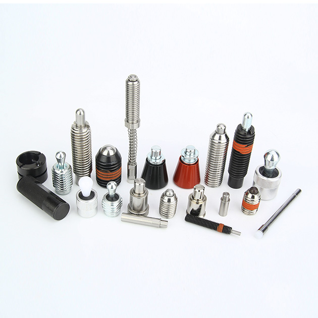
Every manufacturing process demands reliable positioning. Engineers often rely on a critical standard machine element to secure movable components rapidly. We call this mechanism an Indexing Plunger. They appear simple at first glance. However, picking the wrong model carries severe mechanical consequences. Poor selection easily leads to sudden shear failure. It causes operator fatigue during repetitive tasks. It also introduces alignment inaccuracies during daily operation. You must match the hardware to your exact physical demands. This guide provides design engineers and procurement teams an evidence-based framework. You will learn how to evaluate, specify, and source these essential components correctly. We explore sizing rules, material constraints, and dynamic loading limits. Modern automation heavily depends on these localized locking mechanisms.
Key Takeaways
Application Drives Configuration: The choice between standard spring-return and locking (rest position) plungers dictates operational safety and ergonomics.
Material Compatibility is Critical: Selecting between carbon steel, stainless steel, and specialized plastics impacts environmental resilience and galvanic corrosion risks.
Dynamic vs. Static Loads: Shear force ratings must be evaluated against real-world dynamic operational stresses, not just static holding requirements.
Ergonomics Matter: Actuation style (knobs, pull rings, mushroom grips) and spring tension must align with operator frequency and mechanical leverage constraints.
Defining the Application: When to Specify an Indexing Plunger
Manufacturing environments prioritize speed and accuracy continuously. Engineers face constant demand for toolless adjustment mechanisms. Jigs, fixtures, and automated equipment require repeatable positioning daily. Rapid changeovers keep modern production lines profitable. You need a reliable method to locate and lock moving machine parts. Finding the right hardware simplifies complex assembly workflows.
Success depends on three primary technical criteria. First, you must achieve precision alignment. The pin must fit tight tolerances repeatedly. Second, the component needs long-cycle durability. Industrial fixtures often undergo thousands of daily actuations. Finally, it should offer clear tactile feedback to the human operator. Operators must feel a definitive click upon engagement.
How does an Indexing Plunger compare to alternative fastening devices? Let us review the available options objectively. Basic spring plungers use internal pressure to push a ball or nose. They lack manual retraction mechanisms entirely. Ball lock pins allow quick removal from a hole. However, they do not securely thread into a rigid housing. Detent pins offer similar loose-fit limitations. An indexing plunger mounts directly into the solid machine frame. It handles high-shear applications securely. The threaded outer body ensures maximum lateral stability. Operators gain deliberate manual control over the pin engagement process. This deliberate control eliminates accidental machine releases.
Core Configurations: Categorizing Indexing Mechanisms
You must categorize indexing mechanisms by their operational logic. Selecting the correct style prevents costly machine crashes. The internal mechanics vary significantly across different designs. You must understand how the spring interacts alongside the pin body.
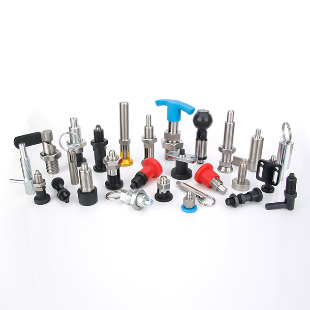
First, consider standard non-locking plungers. The internal pin automatically returns to its fully extended position. It happens the moment the operator releases the top knob. We specify these components for momentary release applications. They provide high-security auto-locking behavior. Imagine an operator accidentally bumping the fixture handle. The pin stays engaged safely inside the receiver hole. You prevent accidental displacement automatically. The system defaults to a secure, locked state.
Next, we evaluate rest position plungers. Many engineers call them locking or cam action plungers. The pin locks firmly in the retracted position. Operators typically pull the knob outward and apply a 90-degree turn. A precision notch inside the metal body holds the pin back securely. We use this style for continuous adjustment tasks. It prevents operator fatigue during lengthy machine setup procedures. You keep both hands completely free to manipulate the heavy machine carriage. The pin remains retracted until the operator turns the knob back.
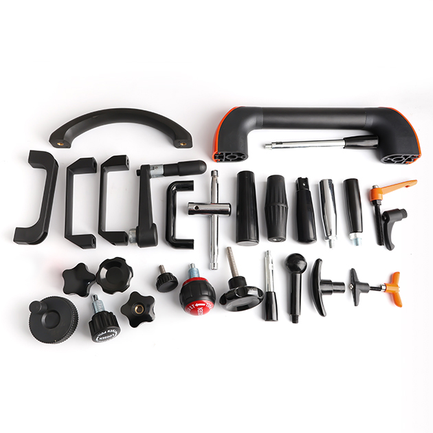
Actuation styles significantly impact daily ergonomic usability. Manufacturers produce diverse handle configurations.
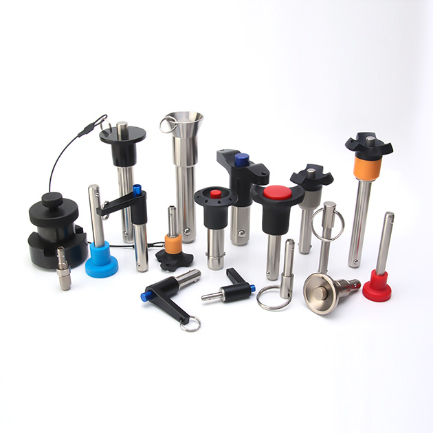
T-handles: Deliver high pull force capability. They work perfectly alongside extremely heavy spring tensions.
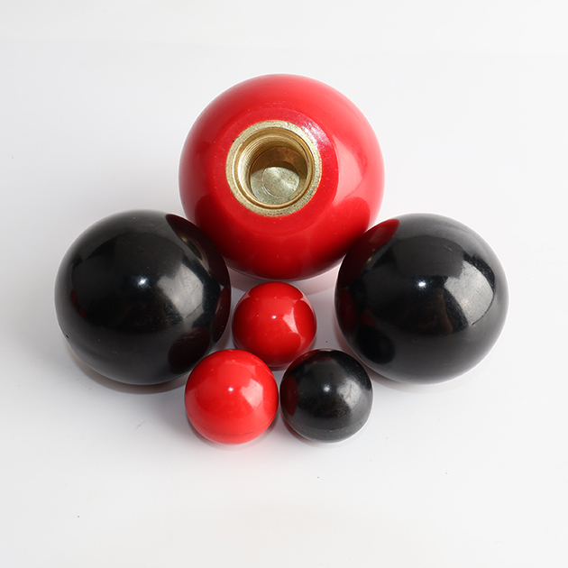
Mushroom grips: Offer an ergonomic grasping surface. Operators palm them comfortably during heavy-duty tasks.
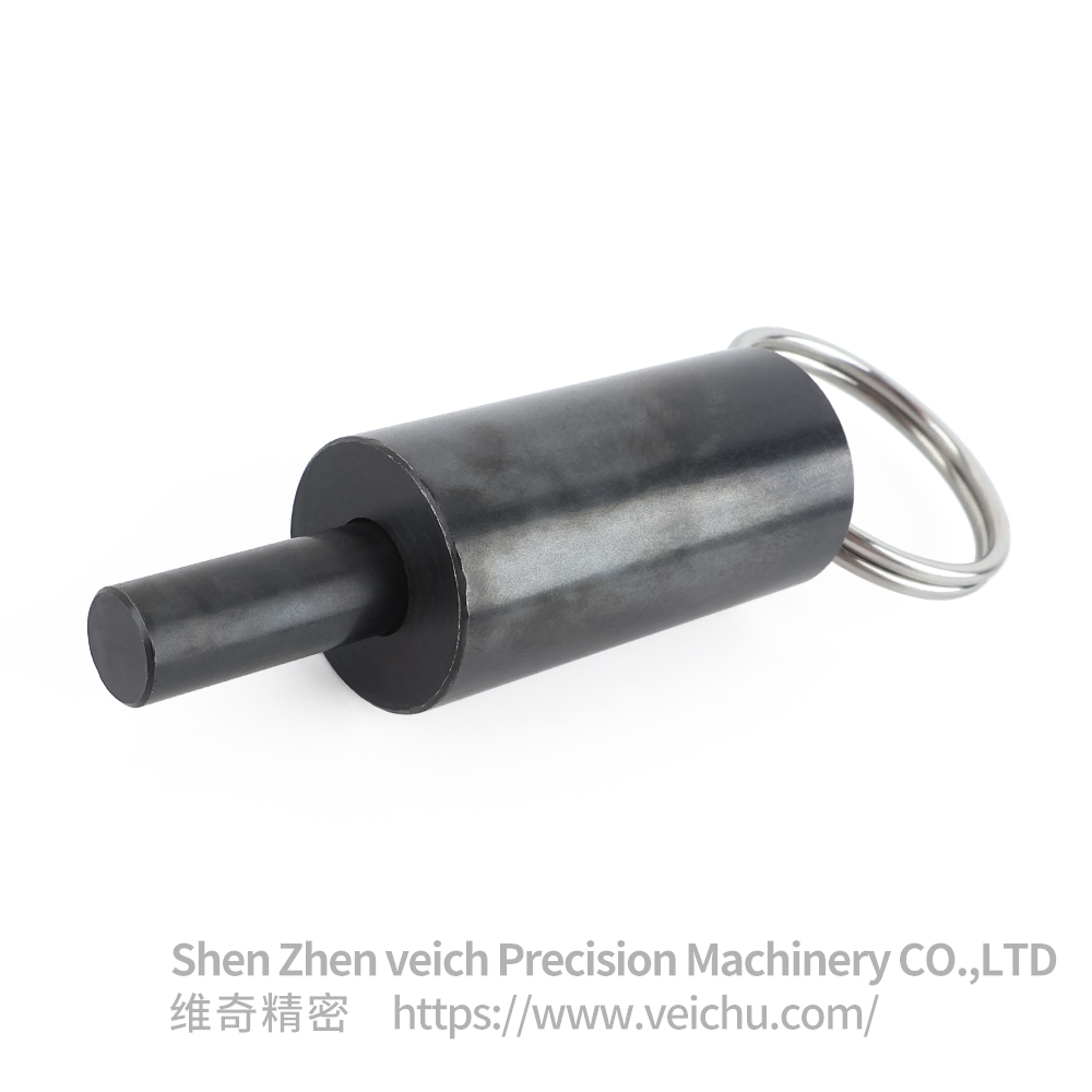
Pull rings: Provide a low-profile spatial solution. They fit into tight spatial envelopes effortlessly.
Draw hooks: Enable remote mechanical actuation. You can connect cables or metal linkages easily.
Evaluation Dimensions for Design Engineers
Design engineers must navigate multiple evaluation dimensions carefully. Your choices determine overall component lifespan. You must analyze the operating environment rigorously.
Let us discuss material selection and environmental compliance. Industrial machinery typically utilizes carbon steel components. Blackened or zinc-plated steel delivers exceptional high shear strength. It suits standard dry industrial environments perfectly. Conversely, cleanrooms and food processing facilities mandate stainless steel bodies. We commonly specify 303 or 316 stainless grades. Stainless resists highly corrosive wash-down environments effectively. However, you must accept a slight engineering trade-off. Stainless steel usually offers slightly lower shear strength than hardened carbon steel. Some modern designs incorporate plastic or polyamide grips. They provide valuable structural weight reduction. They also offer excellent thermal insulation for high-heat zones. Keep an eye on environmental degradation risks. Strong UV exposure or harsh industrial chemicals degrade plastic components over time.
Body Material Type | Primary Benefit | Ideal Operating Environment | Common Specification Mistake |
|---|---|---|---|
Blackened Carbon Steel | Maximum shear load strength | Dry indoor manufacturing floors | Using in highly humid environments |
Zinc-Plated Steel | Moderate ambient rust resistance | General industrial automation use | Exposing to harsh acidic chemicals |
Stainless Steel (303/316) | Extreme corrosion resistance | Cleanrooms and food processing | Ignoring slightly reduced yield strength |
Spring force parameters require careful attention during specification. Engineering sheets distinguish between initial spring force (F1) and final spring force (F2). F1 represents the tension when the pin rests fully extended. F2 represents the tension when fully retracted. You must balance secure holding power against operator fatigue. A massive F1 prevents accidental disengagement entirely. Yet, a massive F2 exhausts the operator pulling the knob repeatedly. You should calculate the expected daily actuation frequency.
Thread specifications influence installation integrity heavily. You will choose between metric and inch systems primarily. Regional manufacturing standards dictate this basic choice. Pay close attention to the specific thread pitch. Fine threads offer superior resistance against vibrational loosening. They also allow for much finer depth adjustment during installation. Coarse threads thread faster into tapped holes but loosen much easier under vibration.
Implementation Risks and Mechanical Realities
Mechanical realities expose poor design choices rapidly. Real-world implementation presents severe engineering risks. You must anticipate dynamic forces acting upon your assemblies.
Shear force limitations represent the most critical failure point. Manufacturers publish static shear load limits in their catalogs. Never rely solely on these static numbers. You cannot use static holding numbers for dynamic impact loads. A moving heavy carriage slamming into the pin generates massive kinetic energy. The steel pin will snap immediately if you ignore dynamic stresses. You must calculate a generous safety factor. Base this safety factor on the specific kinetic energy of your moving application. Consider the carriage mass and its travel velocity.
Vibration causes immediate mechanical loosening problems. High-vibration milling machinery slowly backs threads out of their tapped housing. An unseated Indexing Plunger loses its alignment precision entirely. We strongly recommend robust loosening mitigation strategies. Specify plunger models featuring integrated locknuts. Use chemical thread-locking patches during the final assembly installation. Opt for fine-pitch threads whenever the physical envelope permits.
Contamination frequently causes internal seizing. Open-body designs invite airborne particulate ingress constantly. Metal chips or liquid coolant enter the internal spring cavity. The sliding mechanism quickly jams. We highly recommend fully sealed plungers for dusty environments. Minimized-clearance designs block stray debris effectively. A blocked indexing pin stops your automated production completely.
Shortlisting Logic: A Step-by-Step Decision Framework
Selecting the perfect locking component requires a systematic approach. Follow this step-by-step decision framework closely. It prevents costly procurement errors and engineering rework.
Step 1: Determine the Physical Envelope. Map the strict physical constraints of your machine assembly. Note the exact required pin diameter for your locating receiver hole. Calculate the necessary stroke length for full engagement. Finally, measure the available installation thread size on your metal frame.
Step 2: Lock vs. No-Lock. Assess the daily operator workflow carefully. Does the operator need both hands free? If yes, specify a rest position locking plunger. If safety regulations demand immediate auto-engagement, specify a standard spring-return model.
Step 3: Define the Operating Environment. Apply your material selection logic strictly. Corrosive wash-down areas always demand stainless steel. Dry, high-shear applications require hardened carbon steel. Evaluate ambient room temperatures if utilizing plastic knob components.
Step 4: Review Ergonomics & Next Steps. Match the top grip type to human factors. High interaction frequency requires ergonomic mushroom grips. Direct your engineering team to download the corresponding CAD files. Verify the geometric fit and mechanical tolerances virtually prior to final procurement.
Engineers must double-check clearance fits. The locating hole must be slightly larger than the pin diameter. Too tight, and the pin binds. Too loose, and the carriage wobbles. You achieve precision by machining the receiver hole perfectly.
Conclusion
Successful mechanical implementation requires a highly balanced engineering approach. You must weigh raw shear strength against environmental suitability. Operator ergonomics dictate daily manual production efficiency. We encourage rigorous design validation for every new project. Import 3D CAD models directly into your digital assembly environment. Request comprehensive technical data sheets from your chosen manufacturers. Always verify specific dynamic load ratings before finalizing your structural decisions.
Take action today to optimize your fixture designs. Browse the standard product catalog to filter options by specific physical dimensions. Contact the engineering support team directly for specialized custom configurations. They can modify pin lengths and spring tensions for your unique applications.
FAQ
Q: What is the difference between an indexing plunger and a spring plunger?
A: Indexing plungers feature manual actuation handles or knobs. Operators use them to retract the internal pin deliberately. Spring plungers lack external manual handles entirely. They rely solely on direct side-pressure or external lateral force to depress a ball or pin automatically.
Q: How do I calculate the required shear strength for an indexing plunger?
A: Evaluate the maximum lateral force applied against the pin while locked. Divide this maximum expected force by the pin's physical cross-sectional area. Compare this resulting figure against the material's specific yield strength. Always apply an adequate safety factor for dynamic impact loads.
Q: Can indexing plungers be welded into place?
A: Yes. Manufacturers offer specialized smooth-body, weldable indexing plungers. These specific models lack external installation threads. They are designed for permanent integration directly into steel fixtures, heavy frames, or custom machinery where threaded installation proves impossible.
Q: What is a cam-action indexing plunger?
A: A cam-action model utilizes an internal sloped cam mechanism. It allows smooth retraction and secure resting locking via a simple twist of the handle. This specialized design often offers a more robust and vibration-resistant lock than standard notched rest-position plungers.


