

How Does A Ball Lock Pin Work
Views: 0 Author: Site Editor Publish Time: 2026-07-07 Origin: Site


Heavy industry faces a persistent trade-off between operational efficiency and structural safety, posing a tough engineering challenge: achieving fast assembly and disassembly while maintaining intact joint performance under extreme loads. The ideal solution relies on well-selected industrial quick-release fasteners.
Industrial scenarios including aerospace rigging, heavy machinery and professional tooling require frequent, tool-free disassembly. Conventional fasteners are prone to loosening from equipment vibration, which may trigger severe structural failures. This guide focuses on industrial positive locking mechanisms to address the conflict between quick access and reliable locking, elaborating on their engineering mechanics, performance advantages and selection criteria for high-shear working conditions. Mastery of these principles helps avoid structural failures and optimize reusable industrial applications.
Key Takeaways
Core Mechanism: Ball lock pins utilize a spring-loaded central spindle that forces hardened ball bearings outward to create a secure, positive lock against a receptacle.
Positive vs. Detent: Unlike standard detent pins that rely solely on friction, ball lock pins cannot be removed without intentional button actuation, preventing accidental release under vibration.
Specification Imperatives: Selecting the right pin requires exact calculations of grip length, material shear strength (typically stainless or alloy steel), and handle ergonomics for the operating environment.
The Internal Mechanics: Step-by-Step Operation
Understanding internal geometry reveals why these components excel in high-vibration environments. The design relies on simple physics but requires precise manufacturing tolerances. Let us break down the exact sequence of operation.
The Spindle and Spring Mechanism
Every Ball Lock Pin houses a hidden internal spindle. This spindle runs longitudinally through the center of the pin shank. A heavy-duty compression spring sits at the top of the mechanism. In the default, un-actuated state, the spring exerts constant downward pressure. This pressure forces the widest section of the spindle against hardened ball bearings. The bearings sit in precision-machined holes near the tip. The thick spindle acts as a wedge. It pushes the balls outward beyond the outer diameter of the pin shank. They lock firmly into place.
Actuation: The Release Process
Disassembly requires active manual operation: pressing the handle button compresses the internal spring and drives the spindle forward inside the hollow shank. A narrow recessed channel on the spindle will align with the ball bearings as the spindle moves. Freed from structural support, the balls retract fully into the channel and sit flush with the pin shank, allowing smooth removal of the pin.
The "Positive Lock" Advantage
The positive lock structure delivers unparalleled safety against external interference. Vibration and axial pulling force cannot push the balls to retract, as the thick spindle section forms a rigid mechanical barrier. The locking relies on solid steel structure rather than simple friction, ensuring absolute locking stability. The pin cannot be pulled out by brute force; extreme axial tension will damage the matching holes before the lock fails. Only intentional button pressing can release the lock.
*Placeholder for an exploded-view CAD diagram showing the internal spindle profiles.*
Evaluating Ball Lock Pins vs. Fastening Alternatives
Engineers must justify component selection based on mechanical advantages. Let us evaluate how a Ball Lock Pin performs against traditional alternatives. We focus heavily on structural security and operational efficiency.
Structural Security: Positive Lock vs. Detent Pins
Detent pins look similar externally but function differently. A detent pin uses an internal spring pressing directly against the ball bearings. It relies entirely on friction. If you pull a detent pin hard enough, you overcome the spring tension. The balls push inward, and the pin slides out. This creates a severe risk in heavy machinery. High vibration can slowly work a detent pin loose. Conversely, positive locking requires dual-action release. You must push the button and pull the handle simultaneously. Vibration alone cannot eject it.
Operational Efficiency: Modern vs. Traditional Hardware
Traditional bolts and cotter pins provide excellent holding power. However, they fail in operational speed. Threading a nut requires hand tools. Torquing a bolt demands precision and time. Bending a cotter pin takes effort and damages the pin over multiple uses. You spend minutes on a single connection. A positive locking pin changes this entirely. The operation takes less than a second. Operators press the button, insert the shank, and release. The connection secures instantly. This efficiency shines during complex tooling setups or emergency aerospace maneuvers.
When NOT to Use a Positive Locking Mechanism
Good engineering requires acknowledging limitations. You should not use these mechanisms for permanent structural joints. If a joint requires high continuous axial tension loads, you need threaded bolts. Bolts allow you to apply specific torque to clamp materials tightly together. Locking pins primarily handle shear loads, not clamping force. Additionally, non-critical, low-frequency access points often favor simpler clevis pins. If a joint rarely opens and faces minimal vibration, traditional hardware works fine.
The table below summarizes the key differences between common fastening choices:
Fastener Type | Locking Mechanism | Vibration Resistance | Primary Load Type | Tooling Required |
|---|---|---|---|---|
Positive Locking Pin | Mechanical block (Spindle) | Excellent | Shear | None (Push button) |
Detent Pin | Friction (Spring pressure) | Poor to Moderate | Shear | None (Pull to release) |
Nut and Bolt | Threaded clamp | High (requires locknuts) | Tension / Shear | Wrenches / Torque tools |
Clevis Pin with Cotter | Physical barrier (Cotter pin) | Good | Shear | Pliers (for cotter bending) |
Critical Evaluation Criteria for Sourcing and Specification
Specifying the wrong fastener introduces severe risks. You must evaluate load ratings, physical dimensions, materials, and ergonomics. Careful specification ensures safety and long-term reliability.
Shear Strength and Load Ratings
Engineers must calculate perpendicular shear forces and distinguish single-shear and double-shear scenarios. Double-shear structures bear higher loads. All pin diameters must match calculated stress thresholds per manufacturer specification tables.
Grip Length Calculation
Grip length refers to the usable shank segment from the handle base to extended balls. Undersized grip causes jamming and failed locking; oversized grip leads to joint wobble, inducing metal fatigue and potential failure over time.
Material Selection and Compliance
The operating environment dictates your material choice. You cannot compromise on metallurgical properties.
Alloy Steel: Choose alloy steel for maximum shear strength. It handles heavier mechanical loads. However, it offers lower corrosion resistance. You must keep it lubricated or use it strictly in dry environments.
Stainless Steel (17-4 PH / 300 series): Stainless steel is non-negotiable for demanding environments. Aerospace, marine, and medical applications require it. It resists rust, chemicals, and extreme temperatures. While slightly lower in absolute shear strength than alloy steel, its durability justifies the choice.
Handle Configurations
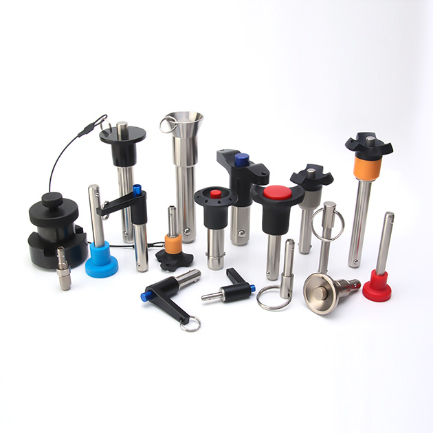
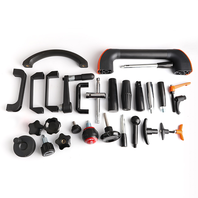
T-handles suit gloved operation with firm grip;
L-handles provide leverage for tight spaces;
Low-profile button handles prevent accidental collision in compact assemblies;
Ring handles support fast repetitive pulling operations.wiftly.
Common Failure Modes, Risks, and Mitigation
Even premium hardware fails under poor conditions. We must anticipate field issues. Understanding common failure modes allows you to implement smart mitigation strategies.
Debris Jamming and Contamination
Industrial dust and metal shavings may jam internal spindles, locking balls in place. Mitigation includes adopting sealed pins and implementing regular cleaning and lubrication maintenance for harsh working conditions.
Binding Under Shear Load
Heavy shear stress clamps balls tightly against receptacle walls, making pin removal impossible even with button actuation. Operators must relieve joint load via jacks or levers before disassembly.
Lanyard Entanglement
Anti-drop lanyards used in aerospace scenarios may snag rotating machinery. Reasonable lanyard routing and proper length adjustment are required to eliminate slack and safety hazards.
Shortlisting Logic and Next Steps for Procurement
Transitioning from engineering design to procurement requires structured logic. You must determine whether standard parts suffice or if custom manufacturing remains necessary.
Standard vs. Custom Tolerances
Commercial-off-the-shelf (COTS) components handle most applications perfectly. Standard fractional or metric diameters provide predictable slip-fit clearances. This prevents binding while maintaining rigidity. However, specialized projects sometimes demand application-specific diameters. If your joint requires zero-play tolerances or unusual grip lengths, you must specify custom machined units. Discuss these requirements directly with the manufacturer.
Prototyping and Testing
Never bypass the prototyping phase. We recommend sourcing sample units initially. Test them in the physical assembly. Verify insertion tolerances manually. Ensure the handle configuration fits the ergonomic workflow of the operators. Real-world testing reveals binding issues that CAD models often hide.
Actionable Next Steps
Do not guess technical specifications. Download the full manufacturer technical spec sheet. Review the 3D CAD models to check spatial clearances. If your joint experiences unusual dynamic loads, consult directly with an application engineer. They will verify your shear load calculations and confirm material compatibility.
Conclusion
The immense value of a Ball Lock Pin lies in its uncompromising blend of operational speed and absolute positive-locking safety.
Successful field implementation depends entirely on accurate measurement of expected shear forces, exact grip length, and specific environmental conditions.
You must actively evaluate the handle ergonomics to match operator constraints, such as tight clearances or heavy gloves.
Take immediate action by utilizing a product configuration tool, downloading high-density specification tables, or scheduling an engineering consultation to finalize your design.
FAQ
Q: Can ball lock pins handle axial tension loads?
A: No, they handle minimal axial loads. Engineers design them primarily to resist perpendicular shear forces. If you subject the joint to significant axial pull, you risk damaging the precision ball retaining holes and compromising the internal mechanism entirely.
Q: What is the difference between single-acting and double-acting ball lock pins?
A: Single-acting pins release only via button pressing. Double-acting models support button release or forced handle pulling, suited for rapid separation working conditions.
Q: How tight should the hole tolerance be for a standard positive locking pin?
A: Adopt standard slip-fit clearance. Excessively tight holes cause binding, while oversize holes lead to joint wobble. Follow manufacturer drill diameter specifications.
Q: Are these locking mechanisms considered fail-safe?
A: They prevent accidental release effectively, but cannot withstand loads exceeding material shear limits. Precise load calculation is still required


