

How Indexing Plungers Assist Quick-Positioning for Automated Production Jigs
Views: 0 Author: Site Editor Publish Time: 2026-09-10 Origin: Site


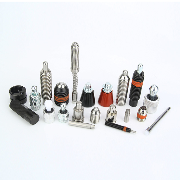
Balancing high-speed cycle times with absolute positional accuracy remains a constant challenge in automated manufacturing environments. Inefficient jig changeovers, misaligned fixtures, and inconsistent manual locking mechanisms routinely disrupt assembly operations. These bottlenecks lead directly to increased machine downtime, elevated scrap rates, and severely compromised production throughput. Custom-machined locking setups often fail to deliver the repeatability required for modern, high-volume production lines. When operators rely on bespoke pins and clamps, the risk of human error multiplies, causing unpredictable variations in part quality. Shifting away from custom mechanisms to standardized components solves this fundamental issue. The indexing plungers serve as critical, off-the-shelf solutions for achieving rapid, repeatable positioning. Integrating these specified components eliminates the guesswork from fixture alignment. They shift the engineering focus from designing complex locking mechanisms to simply selecting the correct specified hardware. This approach ensures fast changeovers, rigid holding forces, and exact alignment across every production cycle.
Selecting the correct indexing plunger requires balancing shear strength requirements with actuation speed to minimize cycle time bottlenecks.
Integration of position sensors (via magnetic plunger pins) is becoming mandatory for closed-loop automated systems to verify lock status before machine operation.
Material selection (e.g., hardened steel vs. stainless steel) dictates the lifespan of the positioning pin under high-frequency lateral loads and harsh environmental conditions.
Mitigating implementation risks involves strict adherence to mounting tolerances to prevent binding and premature spring failure.
Framing the Quick-Positioning Problem in Automation Jigs
Success Criteria for Fixture Changeovers
Successful jig positioning relies on three baseline metrics: changeover speed, operator ergonomics, and exact repeatability. Production lines demand rapid alignment for high-value applications. Locking sliding carriages, indexing rotary tables, and securing adjustable extrusion profiles all require immediate, precise engagement. If an operator spends three minutes fighting a misaligned pin on every changeover, the cumulative lost production time destroys daily quotas. Standardizing on a reliable fixture locating plunger removes the operator skill variable entirely. Workers simply actuate the mechanism, slide the jig into position, and release the handle to lock. This ensures exact alignment every single time, streamlining the entire changeover process and reducing operator fatigue.
Repeatability is the cornerstone of automated assembly. A fixture must return to the exact same micron-level coordinate after every adjustment. Standardized plungers achieve this through precision-ground pins and tightly toleranced housings. When you eliminate the slop inherent in poorly designed custom pins, the machine tools and automated arms interact with the workpiece exactly as programmed. This prevents tool crashes, reduces rejected parts, and maintains strict quality control standards across multiple shifts.
To evaluate success on the floor, measure these specific parameters:
Time required to unclamp, move, and re-lock the fixture assembly.
Physical force required by the operator to actuate the locking mechanism.
Measured deviation in part zero-point after fifty consecutive indexing cycles.
The Cost of Misalignment and Binding
Unsecured jigs suffer heavily from lateral forces and machine vibration. When locking mechanisms fail or loosen, the resulting misalignment damages both the fixture and the workpiece. Inferior setups exhibit severe failure modes over time under heavy industrial use. You will see sheared pins, degraded locating holes, and jammed sliding mechanisms. These failures halt production lines instantly and force expensive, time-consuming repairs. Proper positioning components absorb these lateral loads, maintaining structural integrity during high-speed machining or assembly operations.
Vibration acts as a constant threat to unsecured fixtures. In milling or high-speed stamping operations, harmonic vibrations can cause standard friction clamps to back out. A spring-loaded mechanism actively fights this vibration by applying continuous downward pressure into the locating hole. Without this active engagement, the fixture drifts out of tolerance. The cost of this drift is measured in scrapped material and missed delivery deadlines. Implementing a robust locking strategy prevents these catastrophic shifts.
Consider the mechanical differences between custom shop-made pins and engineered plungers:
Feature | Custom Machined Pin | Engineered Indexing Plunger |
|---|---|---|
Clearance Tolerance | Highly variable based on machinist skill | Standardized (e.g., g6 pin in H7 hole) |
Vibration Resistance | Low; relies on friction or secondary clamps | High; active spring pressure maintains lock |
Replacement Speed | Requires custom fabrication | Off-the-shelf component swap |
Categorizing Indexing Plungers by Actuation and Design
Manual Actuation: Knobs, Pull Rings, and Levers
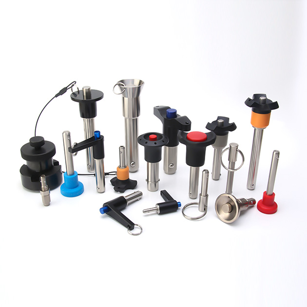
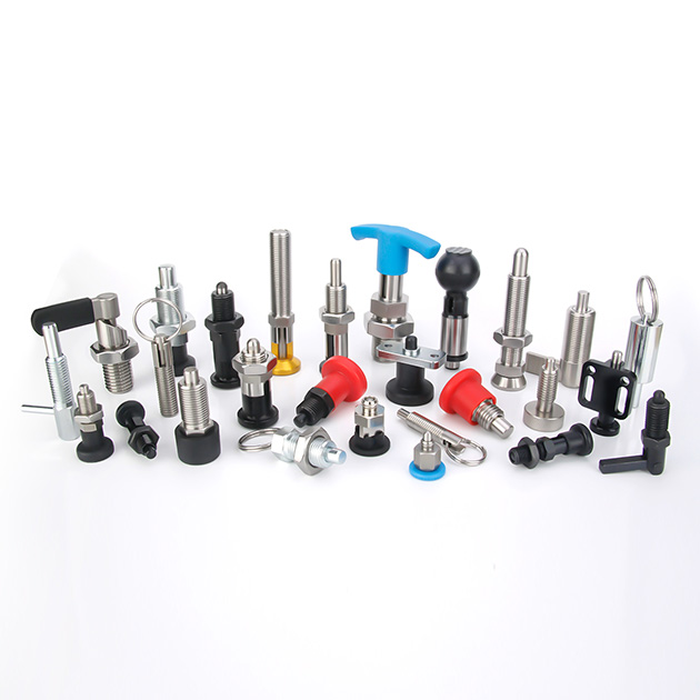
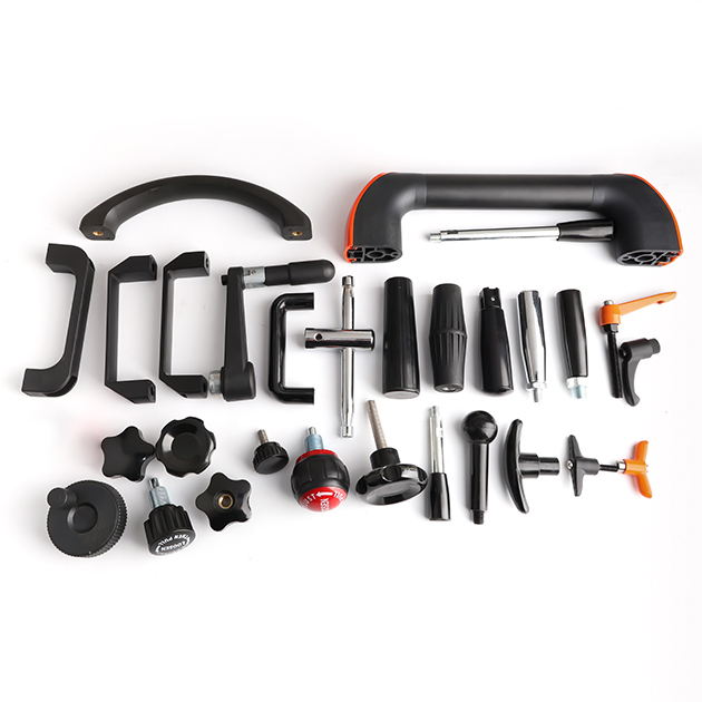
Different applications demand specific ergonomic interfaces based on spatial constraints and actuation frequency. Standard grip knobs work perfectly for low-frequency adjustments where operators have ample hand clearance. Pull rings fit well into incredibly tight spaces where a full mushroom knob would interfere with surrounding machinery or safety guards. Operating levers, utilizing a cam action mechanism, provide fast, secure locking. They also offer clear visual confirmation of the retracted state, allowing floor managers to verify machine status at a glance.
A critical feature in many manual designs is the rest position or locking notch. This mechanism allows the pin to stay locked in the retracted position. Operators pull the knob and twist it 90 degrees, resting the internal pin on a designated notch within the housing. They can then perform hands-free jig adjustments or continuous sliding operations without fighting spring tension. Once the fixture is in the new position, a simple twist releases the spring, firing the pin into the new locating hole.
Actuation Type | Primary Use Case | Ergonomic Advantage | Space Requirement |
|---|---|---|---|
Standard Knob | Low-frequency manual adjustments | Comfortable, full-hand grip | High clearance needed |
Pull Ring | Confined spaces, internal mechanisms | Low profile, single-finger pull | Minimal clearance |
Cam Lever | High-frequency, rapid changeovers | Fast actuation, visual status check | Medium clearance |
Pneumatic | Fully automated, inaccessible areas | Zero manual effort required | Requires air lines/fittings |
The Mechanics of the Spring Loaded Indexing Plunger
The internal mechanics dictate performance reliability and holding power. A spring loaded indexing plunger relies on specific spring rates to maintain holding force against heavy vibration and lateral shear. You will encounter two primary resting states: normally extended and normally retracted. Normally extended pins automatically snap into the locating hole when the jig aligns. The internal spring provides continuous downward pressure, ensuring the pin does not back out during operation. This is the standard configuration for fail-safe locking.
Normally retracted designs operate inversely. The pin remains hidden inside the housing until actuated. This configuration prevents the pin from dragging across the surface of the fixture during long sliding movements, preventing scratches and reducing wear on the pin tip. Engineers must evaluate the spring force carefully. Too weak, and the pin vibrates loose; too strong, and manual actuation becomes an ergonomic hazard for the operator. Initial spring forces typically range from 5 to 20 Newtons, while end-of-stroke forces can exceed 50 Newtons depending on the body size.
Pneumatic and Automated Actuation
Fully automated cells require non-manual solutions to maintain continuous operation. When manual intervention is unsafe, restricted by guarding, or simply too slow, pneumatic plungers take over. These units integrate directly with programmable logic controllers (PLCs) and factory air lines. The controller sends a digital signal to a solenoid valve, actuating the air cylinder and retracting the pin for indexing. Once the rotary table or linear actuator reaches the new coordinate, the air pressure exhausts, and the heavy-duty spring forces the pin back into the locked state.
This synchronized locking and unlocking keeps automated cycles running without human delay. Pneumatic actuation also allows for simultaneous unlocking of multiple fixtures across a large machine bed. A single command can release four corner plungers instantly, a task that would take an operator several minutes to perform manually. Operating pressures usually sit between 4 and 6 bar, making them compatible with standard shop air systems.
Technical Evaluation Criteria for Fixture Locating Plungers
Material Selection and Shear Strength
Evaluating pin materials requires matching the component strictly to the application environment and load profile. Hardened steel pins handle high shear loads and aggressive, high-frequency indexing cycles. They resist deformation when subjected to sudden lateral impacts. Stainless steel variants resist corrosion and chemical degradation, making them ideal for washdown environments in food processing, pharmaceutical manufacturing, or marine applications. Polymer knobs offer significant weight reduction for lightweight, portable jigs where every gram matters.
To calculate the required shear strength, you must analyze the mass and acceleration of the moving jig. The pin must withstand the maximum lateral force generated when the moving mass abruptly stops or changes direction. If a 50-kilogram carriage decelerates rapidly, the resulting kinetic energy transfers directly into the pin shaft. Selecting a pin with a shear yield strength below this threshold guarantees catastrophic failure. Always factor in a safety margin to account for unexpected machine crashes or operator misuse.
Pin Diameter (mm) | Material | Approx. Max Shear Force (N) |
|---|---|---|
5 | Stainless Steel (1.4305) | 1,500 |
6 | Hardened Steel | 3,200 |
8 | Hardened Steel | 5,800 |
10 | Stainless Steel (1.4305) | 6,200 |
Thread Types, Pitch, and Mounting Configurations
Mounting configurations directly impact installation stability and adjustment precision. Fine threads offer precise depth adjustment, allowing engineers to dial in the exact engagement depth of the pin into the locating hole. Coarse threads provide faster installation but lack micro-adjustability. Weldable bodies offer permanent, heavy-duty mounting for structural steel frames, while flange mounts allow for simple bolt-on integration using standard cap screws, facilitating easy replacement if the unit is damaged.
Thread pitch determines the micro-adjustability of the plunger body within the fixture plate. Using spacer rings and lock nuts secures the plunger body firmly in place. This prevents the entire assembly from loosening under high-vibration indexing cycles. When threading a plunger into a blind hole, ensure adequate thread engagement length to distribute the shear load across the housing, preventing thread stripping under heavy lateral forces. Common metric fine threads used in these applications include M10x1.0 and M12x1.5, which provide superior resistance to vibration-induced backing out compared to standard coarse pitches.
Smart Indexing: Position Signals and Sensor Integration
Modern manufacturing demands verifiable, data-driven automation. We are seeing a massive shift toward indexing plunger designs with built-in position signals. These advanced units integrate a small, powerful permanent magnet directly into the internal plunger pin. A compact proximity or Hall effect sensor inserts seamlessly into the plunger housing. This setup feeds real-time lock and unlock status back to the machine controller, achieving closed-loop verification without expanding the component's physical footprint.
This sensor integration acts as a critical safety interlock. The machine PLC will not initiate the next cycle unless the sensor confirms the pin is fully extended and engaged in the locating hole. If a piece of debris prevents the pin from seating completely, the sensor detects the fault and halts the machine, preventing a crash. These sensors typically utilize standard M8 or M12 connectors and carry IP67 ratings, ensuring they survive exposure to cutting fluids and industrial washdowns.
Trade-Offs in Selecting an Automation Jig Component
Component Cost vs. Cycle Time Reduction
Specifying premium components yields a high return on investment when evaluated against operational efficiency. Sensor-integrated or cam-lever types carry a higher initial price tag than standard pull-knob variants. However, the upfront cost of a high-cycle automation jig component is negligible compared to the cost of factory downtime. A jammed pin or a misaligned fixture can halt a production line for hours, costing thousands of dollars in lost output and idle labor.
Investing in reliable, fast-actuating plungers reduces cycle time bottlenecks and eliminates the scrap associated with improper locking. If a premium cam-lever plunger saves an operator 15 seconds per changeover, and the machine undergoes 20 changeovers a day, the time savings accumulate rapidly. Over a year, that single component pays for itself exponentially by keeping the spindle turning and the assembly line moving. Machine shop hourly rates easily exceed a hundred dollars; saving just a few minutes a day justifies specifying the highest quality hardware available.
Form Factor vs. Holding Force
Modern production jigs face severe spatial constraints. Engineers must often fit locking mechanisms into incredibly tight envelopes alongside sensors, pneumatic lines, and clamping cylinders. This creates a strict trade-off between specifying a compact, low-profile plunger and maintaining adequate shear load capacity. Smaller bodies require smaller pin diameters to fit within the housing. A reduced pin diameter inherently lowers the maximum shear strength of the component.
You must evaluate whether the space savings justify the reduction in holding force. If a compact plunger cannot withstand the lateral loads of the application, the jig design must be altered to accommodate a more robust pin. Sometimes, utilizing multiple smaller plungers distributed across the fixture can provide the necessary holding force while maintaining a low profile. CAD clash detection is essential during this phase to ensure the operator still has physical access to actuate the pin.
Implementation Risks and Mitigation Strategies
Contamination and Debris in the Plunger Mechanism
Industrial environments introduce severe contamination risks to mechanical components. Metal shavings, liquid coolant, abrasive dust, and weld spatter can easily enter the spring housing. Once inside, this debris packs around the spring, causing the pin to seize, bind, or fail to extend fully. A seized pin renders the entire quick-positioning system useless and requires immediate maintenance intervention.
To mitigate this risk, specify plungers with protective seals, wipers, or closed-body designs. These features block ingress paths, keeping the internal mechanics clean. Additionally, implement regular maintenance schedules to inspect and clean the mechanisms. Applying the correct dry lubricant prevents dust from sticking to the pin shaft, ensuring consistent, smooth spring actuation even in the harshest machining environments. Avoid heavy greases that attract and hold abrasive particles.
Alignment Tolerances and Binding Issues
Concentricity errors between the plunger body and the receiving locating hole guarantee mechanical failure. If the alignment is off by even a fraction of a millimeter, the positioning pin will bind against the side of the hole during retraction or fail to engage entirely. This binding forces the operator to hammer or pry the fixture, damaging the equipment.
Engineering best practices dictate strict geometric dimensioning and tolerancing (GD&T) for the locating holes. Chamfering the edges of the receiving hole provides a lead-in, helping guide the pin into place and compensating for minor thermal expansion or machining misalignments. Ensure perfectly perpendicular mounting of the plunger body to the fixture plate to prevent angular binding against the pin shaft. Using hardened drill bushings for the receiving holes prevents the pin from wearing out the softer fixture material over time. Standard practice pairs a g6 tolerance on the pin with an H7 tolerance on the receiving hole for a precise, sliding fit.
To implement these quick-positioning solutions effectively and eliminate fixture misalignment, execute the following steps:
Download the exact CAD models for your shortlisted plungers to verify spatial fitment and operator clearance within your jig assembly.
Calculate the maximum lateral shear load of your moving fixture to confirm the selected pin diameter meets the required safety thresholds.
Review your environmental conditions to finalize the material selection, choosing hardened steel for heavy impacts or stainless steel for washdown areas.
Contact an application engineer to validate sensor integration protocols and wiring diagrams for your specific PLC setup.
FAQ
Q: What is the difference between an indexing plunger and a standard positioning pin?
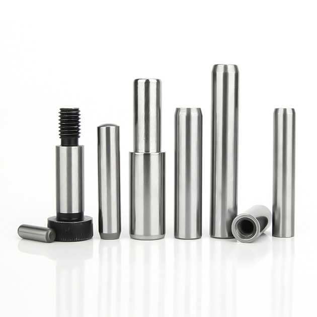
A: A standard positioning pin is a static, solid piece of metal requiring manual insertion and removal. An indexing plunger features an integrated housing, an internal spring mechanism, and an actuation knob or lever. This self-contained design allows the pin to retract and automatically snap back into place, preventing loss of the pin and speeding up the alignment process.
Q: How do I calculate the required shear strength for a spring loaded indexing plunger?
A: You must calculate the maximum lateral force the jig will exert on the pin. Multiply the mass of the moving fixture by its maximum acceleration or deceleration. Compare this force against the shear yield strength of the pin's material and diameter, ensuring you include a safety factor to prevent deformation during sudden stops.
Q: Can indexing plungers be used in high-temperature manufacturing environments?
A: Yes, provided you specify the correct materials. High-temperature applications require all-metal constructions, typically utilizing stainless steel bodies and pins. You must completely remove any polymer components, such as plastic knobs, and ensure the internal spring is rated for high heat. High-temperature dry lubricants should also be used to prevent seizing.
Q: What is the advantage of an indexing plunger with a rest position?
A: The rest position, or locking notch, allows the operator to lock the pin in the fully retracted state. This is highly advantageous for hands-free jig adjustments. The operator does not have to continuously hold the knob against the spring tension while sliding a heavy carriage or aligning a complex fixture.
Q: How do position sensors work inside a fixture locating plunger?
A: Smart plungers integrate a small permanent magnet directly into the internal pin. A compact proximity or Hall effect sensor is inserted into the outer housing. As the pin extends into the locked position, the magnet aligns with the sensor, sending a digital signal to the machine PLC confirming that the fixture is securely locked.
Q: What thread types are standard for an automation jig component like this?
A: Standard thread types include metric fine threads, such as M10x1.0 and M12x1.5, alongside imperial fine threads. Fine threads are preferred because they allow for highly precise depth adjustments when mounting the plunger body into the fixture plate, ensuring the pin engages the locating hole at the exact required depth.


