

Practical Application Scenarios of Ball Lock Pins in Fixture Quick-Release Positioning
Views: 0 Author: Site Editor Publish Time: 2026-09-23 Origin: Site


Machine downtime and labor inefficiencies tied to traditional fixture changeovers kill shop floor productivity. Manual fastening methods require wrenches, torque checks, and constant re-alignment. Shop managers face a constant engineering conflict. We need rigid, high-tolerance part holding to maintain quality. Operational demands dictate rapid, tool-less changeovers in agile manufacturing environments. Traditional bolts and clamps simply take too long to remove and replace.
ball lock pins solve this exact problem. They provide a standardized mechanical solution for quick-release positioning. We are shifting the focus from basic fastening to engineered quick-change systems. These systems guarantee repeatability, positive secure holding, and operator safety. You will learn how to evaluate, select, and implement these components across various industrial scenarios to maximize your production efficiency.
Cycle Time Reduction: Replacing bolted fixtures with push button ball lock pin systems can reduce changeover times by up to 80% while maintaining positional accuracy.
Application Specificity: Successful implementation requires matching the pin's handle style, actuation mechanism, grip length, and material grade to the specific ergonomic and environmental demands of the workstation.
Shear vs. Tensile Loads: Ball lock pins are engineered primarily for high shear strength applications; relying on them for heavy tensile loads requires specific locking mechanisms and rigorous safety evaluations.
System Integration: The reliability of a quick release pin is entirely dependent on the tolerance and hardness of the mating receptacle or drill bushing.
The Mechanics of Quick-Release Positioning in Tooling
Defining the Baseline
Understanding the internal mechanics of a push button ball lock pin is mandatory for proper application. The device consists of a solid hollow shank, an internal spring-loaded spindle, and two or more locking balls near the tip. When at rest, the internal spring forces the spindle downward. The wide section of the spindle pushes the locking balls outward beyond the outer diameter of the shank. This creates a positive lock against the mating surface. Pressing the button depresses the spring and aligns a narrow recess on the spindle with the balls. The balls retract fully into the shank. This actuation allows for zero-clearance insertion and removal without any tools.
The physical sequence of operation follows a strict mechanical path:
The operator depresses the top button, compressing the internal spring.
The internal spindle shifts downward, aligning its narrow channel with the locking balls.
The locking balls fall back inside the shank diameter.
The operator inserts the pin through the aligned fixture holes.
The operator releases the button, forcing the spindle back up and pushing the balls out to lock the plates together.
Single-Acting vs. Double-Acting Mechanisms
Manufacturers typically offer two primary actuation mechanisms. Standard single-acting pins require the operator to push the button to release the locking balls. You then pull the pin out of the fixture. This is the most common configuration for manual assembly tasks. Double-acting variants release the locking balls when you either push or pull the handle. This design suits automated disassembly requirements or workstations where operators wear heavy protective gloves. A firm pull on a double-acting pin automatically disengages the lock, streamlining the removal process in fast-paced environments.
Success Criteria for Fixture Locating Pins
You must evaluate quick-change hardware against strict baseline metrics. Insertion speed dictates how fast an operator can lock a fixture into place. Locking reliability ensures the pin will not back out under machine vibration. Positional repeatability measures how accurately the pin returns the fixture to its zero point after a changeover. A high-quality pin serves a dual role. It acts as a fastener by releasably securing machine components together. Simultaneously, it acts as a locator by providing precision alignment between mating plates. You cannot achieve tight machining tolerances if the pin fails in either role.
Function | Primary Objective | Engineering Requirement |
|---|---|---|
Fastening | Secure plates together to prevent separation. | High shear strength and positive locking engagement. |
Locating | Align plates to a specific zero point. | Tight shank tolerances (e.g., H7) and hardened receptacles. |
The Role of the Quick Change Pin in Lean Manufacturing
Tool-less operation directly supports Single-Minute Exchange of Die (SMED) initiatives. SMED focuses on reducing equipment setup times to less than ten minutes. Replacing threaded fasteners with a quick change pin eliminates the need for hand tools, torque wrenches, and thread cleaning. Operators simply push a button, swap the fixture, and lock the new one in place. This rapid transition drastically reduces operator fatigue during repetitive assembly tasks. When workers spend less time wrestling with bolts, they focus on part quality and machine throughput. Consider a stamping press changeover. Swapping die alignment bolts for quick-release hardware cuts a forty-minute setup down to eight minutes.
High-Impact Application Scenarios for Ball Lock Pins
Modular Welding Fixtures and Jig Assembly
Modular welding tables rely on grid patterns of holes to accommodate temporary jig components. Operators use pins to secure stops, clamps, and angle brackets rapidly. In these environments, standard alloy steel degrades quickly. You must specify a stainless steel ball lock pin to withstand the harsh conditions. Stainless steel resists the adherence of weld spatter, ensuring the pin can still be removed after the welding cycle. High-heat tolerance is mandatory. Extreme temperatures can anneal internal springs, causing them to lose tension. Specialized high-temperature variants maintain their locking force even when positioned near heavy weld zones.
CNC Machining Quick-Change Pallet Systems
CNC mills generate revenue only when the spindle is cutting metal. Quick-change pallet systems allow operators to load parts outside the machine while the previous batch runs. A fixture locating pin is utilized to swap these sub-plates and pallets rapidly. The pins align the pallet to the machine table without losing zero points. In machining applications, concentricity and tight dimensional tolerances are non-negotiable. The shank of the pin must fit the receptacle with minimal clearance. This precise fit prevents the pallet from shifting under heavy cutting forces, ensuring the final machined parts meet dimensional specifications.
Aerospace and Automotive Assembly Line Tooling
Aerospace and automotive manufacturing involve massive components and complex assembly scaffolding. You frequently encounter scenarios involving heavy lifting fixtures and automated guided vehicles (AGVs). Temporary assembly scaffolding must be erected and dismantled quickly as the vehicle moves down the line. Positive-locking mechanisms are an absolute necessity here. Unlike friction-based detent pins, ball lock pins cannot vibrate loose. The internal spindle mechanically blocks the balls from retracting. This prevents accidental release under the constant vibration of power tools, moving AGVs, and overhead cranes.
Transportation Locks and Mobile Fixture Carts
Moving heavy payloads across a factory floor introduces dynamic shifting and transit vibrations. Operators use a quick release pin as a transportation lock to secure mobile fixture carts and modular equipment during transit. When a cart rolls over uneven concrete or expansion joints, unsecured components can bounce and dislodge. The positive secure holding of the locking balls prevents accidental disengagement. Once the cart reaches its destination, the operator simply presses the button to release the lock and deploy the equipment instantly.
Packaging Machinery and Conveyor Guide Adjustments
High-speed packaging lines process multiple box sizes and product formats throughout a single shift. This requires rapid lane adjustments, guide rail swaps, and format changes. Using threaded knobs or bolts for these adjustments is slow and ergonomically taxing for operators. Quick release pins transform this process. Operators slide a guide rail to the new position and drop a pin through the pre-drilled alignment holes. This provides immense ergonomic benefits for operators performing frequent, repetitive adjustments, significantly reducing the risk of repetitive strain injuries.
Technical Evaluation: Selecting the Right Quick Change Pin
Sizing and Grip Length Calculation
Selecting the correct size goes beyond just matching the hole diameter. You must measure the exact grip length, also known as the effective length. This is the distance from the bottom of the handle to the top edge of the locking balls. The grip length must slightly exceed the total thickness of the mating components. If the grip length is too short, the locking balls will not fully clear the bottom plate, and the pin will not lock. If the grip length is too long, it introduces excessive axial play. Improper grip length compromises the positive-locking feature and reduces overall joint rigidity, leading to fixture vibration.
For example, if you are joining a 0.5-inch top plate to a 0.5-inch bottom plate, your total material thickness is 1.0 inch. You should select a grip length of exactly 1.0 inch. The manufacturer builds a slight clearance into the design to ensure the balls deploy just past that 1.0-inch mark.
Material Selection and Environmental Compliance
Material selection dictates the lifespan and strength of the pin. You must evaluate standard alloy steel against stainless steel options based on the working environment.
Material Grade | Key Characteristics | Best Application Scenarios |
|---|---|---|
Alloy Steel (Zinc Plated) | High shear strength, economical, low corrosion resistance. | Indoor manufacturing, dry environments, heavy-duty jigs. |
300-Series Stainless Steel | Excellent corrosion resistance, lower shear strength, non-magnetic. | Food processing, medical equipment, cleanrooms. |
17-4 PH Stainless Steel | High shear strength, good corrosion resistance, heat treatable. | Aerospace tooling, welding fixtures, harsh environments. |
Handle Styles and Ergonomic Considerations
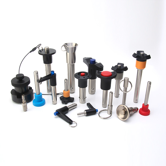
The handle style directly impacts operator efficiency and safety. You must break down the operational trade-offs for each workstation. T-handles provide a full-hand grip, allowing for high pull force when removing pins from tight tolerance holes. L-handles offer a secure grip while maintaining a lower profile, making them ideal for confined spaces. Button handles are compact and sit nearly flush with the fixture, preventing snagging on clothing or moving machine parts. Ring handles allow for easy attachment of retaining lanyards and are suitable for light-duty applications where space is at a premium.
Evaluating Load Capacities
Ball lock pins are engineered to resist lateral forces. You must calculate the required double-shear strength based on the pin diameter and material yield strength. Double shear occurs when the pin passes through three plates, and the load attempts to slice the pin in two distinct places. While shear strength is exceptionally high, you must address the limitations regarding tensile loads. The locking balls are not designed to bear heavy axial loads. If the application involves significant pull-out forces, you must specify heavy-duty detent pins or threaded fasteners instead.
Implementation Risks and Engineering Trade-Offs
Alignment Tolerances and Binding Risks
Precision pins require precision holes. If the mating holes in the fixture plates are misaligned, you face a severe risk of pin binding or galling. Similarly, if the fixture frame flexes under heavy clamping load, the holes will shift out of alignment, trapping the pin. You must implement mitigation strategies to prevent this. The most effective method is using one round pin for primary location and one diamond pin for secondary location. The diamond pin relieves binding stress by locating in only one axis, absorbing minor dimensional variations and thermal expansion between the plates.
Environmental Contamination and Spring Failure
The internal push-button mechanism contains small moving parts and a spring. In aggressive machining environments, metal shavings, sticky coolant, or fine dust can infiltrate the mechanism. This contamination seizes the spindle, rendering the pin inoperable. You must evaluate the trade-off between sealed and standard pins. Sealed or booted pins feature a rubber shroud that protects the internal workings. They have a larger profile. Standard pins require strict maintenance schedules, including regular cleaning and lubrication, to prevent failure.
Cost-Benefit Analysis
Engineered ball lock pins carry a higher upfront unit cost compared to standard bolts and dowel pins. Evaluating the investment requires a broader perspective. You must calculate the return on investment based on labor rates, changeover frequency, and machine hourly rates. If a machine generates hundreds of dollars per hour, saving ten minutes per setup across multiple shifts yields a rapid return. The reduction in machine idle time and the elimination of stripped threads or lost bolts easily justify the initial hardware expenditure for high-volume production cells.
Best Practices for Integrating Fixture Locating Pins
Receptacle and Bushing Design Requirements
Never insert a precision locating pin directly into a soft aluminum or mild steel fixture plate. The repeated insertion and removal will quickly elongate the hole, destroying your positional accuracy. You must use hardened steel or stainless steel drill bushings. Press-fit these bushings into the fixture plates to provide a durable, wear-resistant receptacle. Specify recommended hole tolerances, typically H7 or H8, for the internal diameter of the bushing. This ensures optimal insertion speed while maintaining minimal slop or radial play.
Safety and Tethering Protocols
Loose hardware on a factory floor is a safety hazard and a production risk. Dropped pins can fall into moving machine parts, causing catastrophic damage. Outline strict tethering protocols for all quick-change hardware. Use wire rope lanyards and retaining cables to secure the pins directly to the fixture frame. This prevents Foreign Object Debris (FOD) in critical assembly zones, particularly in aerospace and automotive applications. Tethering also ensures the operator never wastes time searching for a misplaced pin during a critical changeover.
Maintenance and Inspection Schedules
High-cycle manufacturing environments degrade mechanical components over time. Establish rigorous criteria for inspecting your quick-change hardware. Implement a monthly preventative maintenance checklist:
Check for flat spots or excessive wear on the locking balls.
Test the spring tension degradation by pressing the button; it should feel firm and return instantly.
Inspect the main shaft for deep scoring or galling, which indicates misalignment in the fixture.
Verify that the lanyard or retaining cable is securely crimped and free of fraying.
Clean the internal mechanism with compressed air and apply a light machine oil.
Replace any pin that shows signs of sticking or compromised locking action immediately to maintain safety and accuracy.
Conclusion
Download 3D CAD models from the manufacturer to verify clearances and integrate the pins directly into your digital fixture assemblies.
Request physical samples of different handle styles to conduct ergonomic testing with your assembly line operators.
Specify and order the corresponding hardened drill bushings to ensure your fixture plates maintain long-term positional accuracy.
Contact application engineers to verify your double-shear load calculations for any heavy-duty or high-vibration tooling scenarios.
FAQ
Q: What is the difference between a detent pin and a push button ball lock pin?
A: A detent pin uses a friction-based spring mechanism to push the balls outward. You simply push it in and pull it out with force. A push button ball lock pin utilizes a positive-locking mechanical engagement. An internal solid spindle blocks the balls from retracting until the operator physically depresses the button, making it vastly more secure against vibration.
Q: How do you calculate the shear strength required for a fixture locating pin?
A: You calculate shear strength utilizing the pin's cross-sectional area and the material's yield strength. For a double-shear application, where the pin passes through three plates, the load acts on two separate cross-sections of the pin. You multiply the single shear strength by two to determine the maximum lateral load the pin can withstand before shearing.
Q: How do I determine the correct grip length for a quick release pin?
A: Measure the total combined thickness of the mating materials the pin will pass through. Select a grip length that exactly matches this total thickness. The manufacturer builds in the necessary clearance. This ensures the locking balls fully deploy beyond the bottom plate without leaving excessive slack that could cause the fixture to rattle.
Q: Can a stainless steel ball lock pin be used in high-temperature welding fixtures?
A: Standard stainless steel pins can suffer material degradation in extreme heat. Temperatures above 400°F can anneal the internal springs, causing them to lose tension and fail to lock. For high-temperature welding fixtures, you must specify specialized high-temp variants equipped with heat-resistant springs and 17-4 PH stainless steel bodies.
Q: What hole tolerance is required for a standard quick change pin?
A: Standard industry clearances typically require an H7 or H8 hole tolerance for precision locating applications. This provides a slip fit that is tight enough to ensure accurate alignment but loose enough for manual insertion. You must use hardened steel drill bushings to maintain this tight tolerance over thousands of cycles.
Q: Are quick change pins suitable for lifting applications?
A: Standard pins are engineered for high shear loads, not heavy tensile loads. The locking balls cannot support massive overhead weight. Therefore, standard ball lock pins are generally not rated for overhead lifting. If lifting is required, you must use specialized lifting pins that carry specific safety certifications and load ratings.


