

Universal Ball Installation Tips for Material Conveying and Transfer Equipment
Views: 0 Author: Site Editor Publish Time: 2026-09-16 Origin: Site


Multi-directional material handling requires precise execution on the facility floor. The efficiency of a transfer table or conveyor intersection relies entirely on the structural integrity of its omnidirectional components. Improper specification or flawed installation of multi-directional rollers leads to uneven load distribution. This causes point-loading failures, premature bearing wear, and costly unplanned downtime in high-throughput industrial facilities.
Mitigating these risks requires a rigorous, engineering-first approach. You must calculate spacing accurately, select appropriate mounting configurations, and match materials to the operating environment. This guide details the technical requirements for installing a universal ball system. Following these protocols guarantees operational longevity and ensures worker ergonomic safety. We will cover load distribution math, pitch calculations, and environmental matching to keep your conveyor lines running without interruption.
Load Distribution Math is Non-Negotiable: Safe working load calculations must assume that only three units carry the entire payload weight at any given time, regardless of the total number of units under the object.
Pitch and Spacing Dictate Stability: The distance between units must be calculated by dividing the narrowest dimension of the conveyed object by 3.5 to prevent tipping and surface gouging.
Mounting Styles Must Match Operational Stress: Selecting between a threaded ball transfer, flange mount, or drop-in configuration depends strictly on shock-loading potential, frame thickness, and required maintenance accessibility.
Environmental Factors Drive Material Selection: Standard carbon steel fails in washdown or high-debris environments; stainless steel or nylon load balls are required to prevent galvanic corrosion and particulate jamming.
Evaluating Specifications for Your Conveyor System
Selecting the correct hardware dictates the lifespan of your entire transfer table. You must establish baseline requirements before drilling a single mounting hole. These baselines include load capacity, operational speed, and directional shift frequency. Guesswork during this phase guarantees mechanical failure.
Defining Success Criteria
Engineers must define what constitutes a successful installation for their specific facility. A high-speed sorting hub has vastly different requirements than a heavy-duty metal stamping plant. You must measure the maximum payload weight, the average dimensions of the conveyed objects, and the expected throughput rate. Document the ambient temperature, humidity levels, and potential exposure to chemicals. These environmental metrics directly influence hardware selection. Without strict success criteria, facilities often overspend on unnecessary heavy-duty units or underspend on units that fail prematurely.
You also need to evaluate the surface condition of the materials you plan to move. A rough cast-iron engine block interacts with a roller differently than a smooth sheet of polished aluminum. The hardness of the conveyed material must exceed the hardness of the load ball, or you risk gouging the product surface during transit.
Dynamic vs. Static Load Ratings
Understanding manufacturer load ratings prevents catastrophic system failure. Static load refers to the maximum weight a unit can support while stationary. Dynamic load refers to the weight it can support while in motion. You must base your engineering calculations entirely on the dynamic load rating.
When selecting a universal ball roller, you must apply a safety factor. Shock loads and uneven conveying surfaces multiply the stress on individual bearings. If a heavy die drops onto the table, the instantaneous force far exceeds the static weight. Furthermore, dynamic load capacity degrades at speeds exceeding one meter per second. High speeds generate internal friction. This heat causes the internal support bearings to skid rather than roll, accelerating wear and reducing the effective load limit.
Conveying Speed (m/s) | Dynamic Load Capacity Retention | Friction Heat Generation | Recommended Application |
|---|---|---|---|
0.1 - 0.5 | 100% | Minimal | Heavy die handling, manual assembly stations |
0.6 - 1.0 | 90% | Moderate | Standard warehouse logistics, package sorting |
1.1 - 1.5 | 75% | High | High-speed automated routing (requires frequent lubrication) |
1.5+ | Not Recommended | Extreme (Risk of bearing seizure) | Alternative conveying methods required |
Material Selection and Environmental Matching
Hardware materials must match the operational environment. Specifying the wrong material guarantees premature failure. Carbon steel provides the highest load capacity. It is the standard choice for dry, climate-controlled warehouses. However, carbon steel rusts rapidly if exposed to moisture. Stainless steel is mandatory for corrosive environments. Food processing plants and chemical handling facilities require stainless steel to survive harsh washdown procedures.
Nylon or acetal load balls handle delicate surfaces. They prevent scratches on glass or polished sheet metal, though they offer a significantly reduced load threshold compared to steel. When handling materials like untreated wood or soft plastics, a nylon ball prevents the roller from digging into the bottom of the payload.
Material Type | Primary Application | Load Capacity | Environmental Resistance |
|---|---|---|---|
Carbon Steel | Standard logistics, dry warehouses, climate-controlled zones | Maximum | Low (Prone to oxidation and rust) |
Stainless Steel | Food-grade applications, washdown zones, corrosive environments | High | Excellent (Resists chemical washdowns) |
Nylon / Acetal | Glass manufacturing, polished sheet metal, delicate surfaces | Moderate | High (Prevents surface marring) |
Industry-Specific Compliance and Use Cases
Different industries enforce strict operational standards. Air cargo and freight facilities require heavy-duty units designed specifically for Unit Load Device (ULD) decks. These units must withstand extreme impact forces from forklifts and heavy cargo containers. They often feature reinforced steel housings and oversized support bearings to handle the abuse of airport tarmacs.
Conversely, cleanrooms and electronics manufacturing facilities require non-shedding, lubrication-free units. These environments cannot tolerate particulate contamination. A standard lubricated steel unit would release microscopic oil droplets and metal dust, ruining sensitive electronic components. In these settings, engineers specify sealed acetal units that operate completely dry.
Calculating Spacing and Layout for a Roller System
Mathematical precision during the layout phase prevents operational bottlenecks. Incorrect spacing causes conveyed objects to sag, jam, or tip over. You cannot guess the distance between rollers; you must calculate it based on the physical properties of your heaviest and smallest payloads.
The "Rule of Three" for Load Distribution
The "Rule of Three" is a fundamental engineering principle in multi-directional material handling. The bottom surface of a conveyed object is rarely perfectly flat. Wooden pallets warp. Steel plates bend. Cardboard boxes sag. Because of these surface irregularities, you cannot assume the load distributes evenly across all rollers under the object.
You must assume that only three units carry the entire payload weight at any given time. To calculate the minimum required load capacity per individual unit, divide the total object weight by three. If a steel die weighs 1500 kilograms, each individual unit must possess a dynamic load capacity of at least 500 kilograms. Ignoring this rule guarantees point-loading failures and shattered internal bearings. Even if your layout places twenty rollers under the die, surface warping means seventeen of those rollers might not touch the metal at all.
Determining Optimal Pitch (Spacing)
Pitch refers to the exact distance from the center of one roller to the center of the next. You must calculate the maximum allowable distance between units to maintain stability. The formula is straightforward: divide the narrowest dimension of the conveyed object by 3.5.
If the smallest box on your line measures 700 millimeters in width, dividing 700 by 3.5 yields a maximum pitch of 200 millimeters. This spacing ensures that a minimum of three units always support the narrowest part of the object. You must adjust this pitch for highly flexible or compressible materials. Cardboard or thin plastic will sag between rollers if the pitch is too wide. For flexible materials, reduce the calculated pitch by an additional 20 percent to prevent surface gouging.
Grid Patterns vs. Staggered Layouts
Engineers typically choose between two primary layout patterns based on the shape of the conveyed materials. The choice impacts both the structural support of the payload and the total hardware required for the build.
Layout Pattern | Visual Structure | Best Suited For | Hardware Density |
|---|---|---|---|
Square Grid | Straight rows and columns aligned at 90-degree angles. | Uniform, rigid objects with predictable, straight travel paths. | High (Requires more units per square meter). |
Diamond / Staggered | Alternating rows offset by half the pitch distance. | Irregular shapes, cylindrical objects, and multi-directional routing. | Optimized (Provides denser support with fewer total units). |
A square grid simplifies installation and makes measuring pitch straightforward. Fabricators prefer it for standard rectangular pallets. A staggered layout provides denser support for irregular shapes. It reduces the total number of units required per square meter while maintaining the same level of support. This optimizes hardware usage without sacrificing performance.
Mounting Configurations and Installation Methods
The physical installation dictates how well the system absorbs operational stress. Selecting the wrong mounting style compromises the structural integrity of the entire transfer table. You must match the mounting hardware to the thickness of your deck and the expected impact forces.
Threaded Ball Transfer Installation
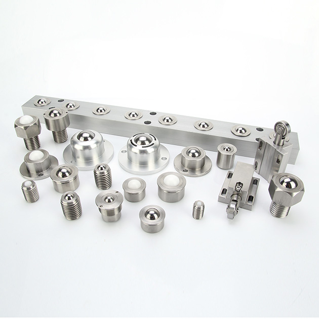
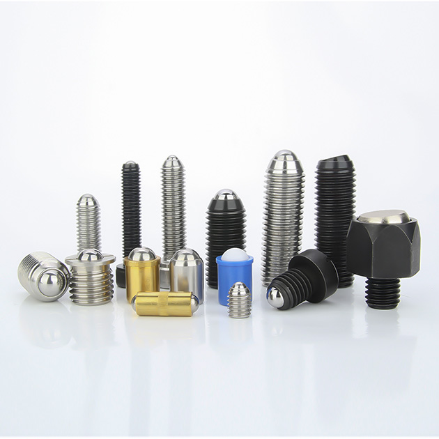
A threaded ball transfer features a threaded stud protruding from the base. This configuration is ideal for applications requiring precise height adjustment. By turning the unit on its threads, you can level the conveying plane perfectly. It is also the best choice for mounting through thick structural cross-members where a standard flange cannot reach.
Installation requires strict adherence to torque specifications. Over-tightening the stud can distort the bearing housing, causing the main ball to seize. Under-tightening allows the unit to vibrate loose during operation. Installers must use locking nuts and apply vibration-resistant thread lockers to ensure the units remain secure under heavy dynamic loads.
Drill mounting holes 1mm larger than the stud diameter to allow for minor lateral alignment adjustments.
Apply a medium-strength thread locker to the stud threads before inserting them into the deck.
Thread the primary locking nut onto the stud from the underside of the deck.
Use a calibrated torque wrench to tighten the nut to the manufacturer's exact specification.
Verify the height of the load ball using a laser level, adjusting the nut as necessary before the thread locker cures.
Flange and Drop-In Mounting Techniques
Flange mounts offer different structural advantages depending on the deck design. Drop-in units feature a base flange. Installers recess these units into a pre-punched deck. This configuration is best for low-profile material handling ball transfer tables where vertical space is limited. Drop-in mounting requires highly precise hole tolerances. If the punched hole is too large, the unit will shift laterally under load, causing premature wear.
Top flange units secure directly to the top surface of the deck via rivets, bolts, or self-tapping screws. This style provides exceptional stability against lateral forces. It is easier to retrofit onto existing tables because it does not require precise recessing. However, the fasteners sit above the deck surface, which can interfere with overhanging loads if not properly countersunk.
Tolerance and Deck Leveling
A transfer table must present a perfectly planar surface. If one unit sits higher than the rest, it absorbs the entire weight of the passing object. This isolated point-loading destroys the conveyor ball roller instantly.
Installers must use precision tools to ensure deck leveling. Set up a rotary laser level across the transfer table. Take elevation measurements at every grid intersection. Use stainless steel shims under flange-mounted units to correct minor deviations. For threaded units, adjust the locking nuts until the top of every load ball aligns perfectly with the laser plane. Do not rely on standard bubble levels for large transfer decks; they lack the precision required for high-load applications. A deviation of just 2 millimeters across a 3-meter table will cause heavy payloads to stall or damage the elevated rollers.
Mitigating Implementation Risks in Transfer Systems
Industrial environments present numerous hazards that threaten the longevity of multi-directional rollers. Proactive risk mitigation prevents sudden mechanical failures. You must anticipate how the system will react to abuse, contamination, and improper usage.
Managing Shock Loading
Heavy loads dropped onto the transfer deck cause severe point-impact damage. Standard units cannot absorb this kinetic energy. The impact forces the main ball down into the smaller support bearings, scoring the internal cup and ruining the unit.
To mitigate this risk, integrate spring-loaded units into high-impact zones. These specialized units feature internal Belleville washers or heavy-duty coil springs. When a load exceeds a predetermined threshold, the main ball retracts into the housing. This transfers the impact force directly to the table deck rather than the internal bearings. Once the shock dissipates, the spring pushes the ball back into its operational position. Place these spring-loaded units specifically at crane drop zones or forklift loading edges.
Environmental Contamination and Debris
Dust, metal shavings, and liquids easily enter the main bearing cup. Once inside, this debris mixes with the internal lubricant to form an abrasive paste. This paste grinds down the support bearings, eventually causing complete seizure.
Mitigate contamination by installing units equipped with self-cleaning debris holes, commonly known as weep holes. These holes allow small particulates and liquids to fall through the bottom of the housing. In environments with heavy dust or metal flakes, specify units with internal felt seals or dirt shields. These seals sweep the main ball clean as it rotates, preventing debris from entering the internal raceway.
Orientation Restrictions
Standard units rely on gravity to keep the support bearings seated in the internal cup. If you install a standard unit upside down, the support bearings drop away from the main load ball. This causes immediate friction, binding, and mechanical failure.
You cannot use standard units for inverted applications. If your process requires floating heavy dies into a press machine from above, you must specify specialized "ball-down" units. These inverted units feature internal recirculating tracks or specialized retaining cups that hold the support bearings against the main ball regardless of gravity. Always verify the orientation rating with the manufacturer before installation.
Symptom | Likely Cause | Immediate Action Required |
|---|---|---|
Loud grinding noise during operation | Debris trapped in the internal bearing cup | Blow out weep holes with compressed air; check felt seals. |
Load ball refuses to rotate (seized) | Point-loading impact or severe corrosion | Replace unit immediately; verify deck leveling. |
Deep scratches on the conveyed payload | Scored load ball or incorrect material selection | Swap steel units for nylon/acetal units. |
Unit vibrating loose from the deck | Missing thread locker or under-torqued nut | Re-torque to spec and apply medium-strength thread locker. |
Ergonomics and Safety
Properly engineered transfer tables significantly improve workplace safety. Reducing physical strain on operators is a primary benefit of omnidirectional handling systems. When workers do not have to fight friction, the risk of musculoskeletal injuries drops dramatically.
Reducing Manual Push/Pull Forces
Moving heavy materials manually causes severe joint and muscle injuries over time. Precision-machined ball transfer unit hardware minimizes both starting inertia and rolling resistance. Starting inertia is the force required to get a stationary object moving. Rolling resistance is the force required to keep it moving.
High-quality units feature polished internal raceways and perfectly spherical support bearings. This drastically lowers the coefficient of friction. A properly leveled and spaced table allows a single operator to rotate and push a 500-kilogram load with minimal physical effort. Aligning your system specifications with occupational safety standards reduces worker fatigue. It prevents strain injuries and ensures compliance with manual handling regulations. You must measure these forces during the commissioning phase to prove the system meets ergonomic safety targets.
Testing, Validation, and Maintenance Protocols
Installation does not end when you tighten the last bolt. Rigorous testing and preventative maintenance ensure the system performs to its engineered specifications over the long term. A neglected transfer table will degrade rapidly, regardless of the initial build quality.
Post-Installation Load Testing
Never put a new transfer table straight into production without validation. Execute controlled runs using maximum payload weights. Push the heaviest expected objects across the entire grid.
During these test runs, monitor the system for acoustic anomalies. Listen closely for grinding, clicking, or scraping sounds. A smooth system produces a low, consistent hum. Grinding indicates debris in the raceway. Clicking suggests a shattered support bearing. Scraping usually means the conveyed object is sagging and hitting the metal housings. Identify and correct these issues immediately before full production begins.
Friction and Inertia Baselines
Establish a performance baseline immediately after installation. Use a digital push-pull gauge to measure the exact force required to initiate movement on a standard load. Record this starting inertia value.
Measure the force required to keep the load moving at a steady pace. Record this rolling inertia value. Keep these baseline metrics in the maintenance log. During future inspections, technicians will repeat these measurements. If the required push force increases by more than 15 percent, it indicates internal bearing wear, lubrication failure, or deck settling.
Preventative Maintenance Schedules
Consistent maintenance prevents catastrophic breakdowns. Establish a strict preventative maintenance schedule based on operational hours and environmental conditions.
Maintenance Task | Frequency | Procedure Details |
|---|---|---|
Visual Surface Inspection | Weekly | Check main load balls for deep scratches, scoring, or rust. Replace damaged units immediately. |
Clear Weep Holes | Monthly | Use compressed air (90 PSI) to blow out debris from the bottom weep holes. |
Lubrication Application | Quarterly | Apply light machine oil to steel units. Do not use heavy grease. Leave nylon units dry. |
Fastener Torque Check | Bi-Annually | Use a torque wrench to verify all mounting bolts and locking nuts meet original specifications. |
Deck Leveling Audit | Annually | Set up a rotary laser level to verify the deck has not settled or warped under heavy use. |
Conclusion
Audit your current or proposed transfer table dimensions to ensure they align with your maximum payload requirements. Calculate your required pitch and load per unit using the Rule of Three to guarantee adequate support and prevent point-loading. Select mounting hardware that matches your deck thickness and shock-loading potential, prioritizing spring-loaded units for high-impact zones. Establish baseline push-pull metrics immediately after installation to monitor future wear and tear accurately.
FAQ
Q: How do you calculate the required load capacity for a universal ball?
A: Divide the maximum weight of the conveyed object by three. Due to surface irregularities, you must assume only three units are supporting the load at any given moment. This ensures no single unit exceeds its dynamic load rating during operation.
Q: What is the difference between a ball transfer unit and a conveyor ball roller?
A: These terms are largely synonymous in material handling. Both refer to omnidirectional load-bearing spheres housed in a fixture, though "conveyor ball roller" is often used colloquially in warehouse logistics, while "ball transfer unit" is the standard engineering term.
Q: When should I use a threaded ball transfer over a flange mount?
A: Use a threaded ball transfer when you need to fine-tune the height of individual units to achieve a perfectly level conveying surface, or when mounting through thick structural cross-members where a flange cannot sit flush.
Q: Can a universal ball roller be installed upside down?
A: Standard units cannot be installed upside down, as the internal support bearings will drop away from the main load ball, causing friction and failure. You must specify purpose-built "inverted" or "ball-down" units for these applications.
Q: How do I prevent debris from jamming a material handling ball transfer?
A: Specify units equipped with internal dirt seals and bottom weep holes. For extreme environments, utilize units with larger clearance tolerances or self-cleaning designs that allow particulates to pass through the housing.
Q: Do universal balls require lubrication?
A: Most carbon and stainless steel units are pre-lubricated at the factory and require periodic re-lubrication with light machine oil. However, units operating in dusty environments or utilizing nylon load balls are often run dry to prevent dust from adhering to the lubricant.
Q: How do ball transfer units improve workplace ergonomics?
A: By providing omnidirectional movement with extremely low friction, they significantly reduce the manual push and pull forces required by operators to position heavy loads, thereby lowering the risk of strain injuries.


