

Common Uses of Spring Plungers in Industrial Machinery and Assembly Lines
Views: 0 Author: Site Editor Publish Time: 2026-09-11 Origin: Site


Micro-misalignments, component slippage, and inconsistent part ejection cause massive headaches on the shop floor. These seemingly minor issues compound rapidly, leading to machinery downtime and rejected parts. Selecting an inadequate locating or holding mechanism accelerates tooling wear. It damages expensive workpieces and disrupts automated workflows. Incorrect spring force, improper material selection, or the wrong nose type all contribute to premature mechanical failure.
Integrating correctly specified spring plungers optimizes cycle times and ensures repeatable accuracy. These components reduce maintenance overhead in complex assembly operations. They provide consistent pressure and precise alignment across millions of cycles. This guide breaks down the technical evaluation criteria for selecting the right plunger for specific industrial applications. You will learn how to match plunger specifications directly to operational demands.
Key Takeaways
Application Dictates Nose Type: Ball plungers are optimal for rolling contact and detent applications, while pin-style plungers provide the extended stroke necessary for ejection and heavy-duty locating.
Material Selection is Mission-Critical: Operating environments dictate body and spring materials; a stainless steel spring plunger is mandatory for washdown, corrosive, or extreme temperature environments.
Force vs. Stroke Trade-offs: Engineers must balance initial and final spring forces with the required travel distance to prevent spring fatigue and ensure consistent holding pressure.
Manual vs. Automated Actuation: Hand-retractable plungers are essential for quick-change tooling and rapid fixture adjustments, eliminating the need for secondary hand tools.
Vibration Mitigation: High-speed assembly lines require plungers with integrated thread locking mechanisms (like nylon patches) to prevent backing out during continuous operation.
The Role of Spring Plungers in Modern Manufacturing
Success Criteria for Industrial Locating and Holding
Mechanical positioning components must meet strict baseline requirements to function effectively in harsh industrial environments. When you design a fixture, you cannot afford slop or drift. Repeatability is the foremost metric. A plunger must return a workpiece to the exact same spatial coordinate during every single cycle, whether it is the first shift or the thousandth hour of operation. Precision dictates the allowable tolerance stack-up within the fixture. Cycle life determines how long the internal spring and nose can operate before fatigue sets in. High-performance plungers routinely exceed hundreds of thousands of cycles without losing their specified spring rate.
You need to understand the difference between static holding, dynamic interaction, and dynamic guiding to specify the right hardware. Static holding secures a part firmly in place for heavy machining operations like milling or drilling. Dynamic interaction involves indexing, ejecting, or detenting where the plunger actively moves to perform a function. Dynamic guiding aligns components as they move continuously through a manufacturing line. Each function requires a distinct approach to plunger selection.
Standardizing these parts across your shop floor cuts custom machining costs. Toolmakers stop wasting hours turning custom spring-and-ball detents on a lathe. Using off-the-shelf plungers simplifies Bill of Materials (BOM) management. It streamlines procurement and ensures replacement parts are readily available in the tool crib during tight maintenance windows.
Repeatability: The ability to hit the exact same location coordinate over millions of cycles.
Precision: Maintaining tight tolerances to prevent part shifting during machining.
Cycle Life: The durability of the internal spring and nose material under continuous load.
Holding Force: Providing adequate pressure without deforming the workpiece.
Core Applications in Industrial Machinery and Assembly Lines
Precision Indexing, Guiding, and Positioning
Rotary index tables and linear transfer systems rely heavily on accurate mechanical stops. A positioning plunger locks fixtures into exact coordinates before any machining or assembly steps occur. The plunger nose engages directly with mating detents or machined grooves on the moving table. This engagement provides a rigid, repeatable zero-point. If the table is off by even a fraction of a millimeter, the entire batch of parts is ruined.
These components also act as guides to align moving parts along a track. As a pallet moves down a conveyor, the plunger applies continuous lateral pressure. This pressure keeps the pallet tracking straight against a datum rail. Minimal side-play in the plunger tip is necessary to maintain tight tolerances. Excessive clearance between the plunger nose and body introduces slop, which degrades positional accuracy and causes uneven wear on the conveyor rails.
Ejection and Part Removal
Stamping dies, injection molding machines, and automated press operations require reliable part ejection. After a forming cycle completes, finished parts often stick inside cavities due to vacuum forces or thermal expansion. A spring loaded plunger provides the necessary mechanical push to free the component. The plunger compresses during the mold closing or stamping phase, storing kinetic energy.
When the die opens, the internal spring releases. The extended stroke of pin-style plungers breaks the vacuum or friction holding the finished part. This facilitates easy removal by robotic arms or gravity drop-offs. Proper spring force calculation ensures the plunger pushes the part clear without denting or deforming the freshly molded material. If the spring is too weak, the part sticks. If it is too strong, you get ejector pin marks on your finished product.
Lateral Holding in Space-Constrained Environments
Many tooling setups lack the overhead clearance required for traditional vertical clamping. Spindles, drill bits, or robotic end-effectors often interfere with top-mounted clamps. Lateral spring plungers solve this problem by applying horizontal force. They secure workpieces firmly against vertical datum faces without getting in the way of the cutting tool.
This implementation is highly effective during light machining or automated assembly where space is strictly limited. The plunger mounts horizontally within the fixture base. As the operator drops the part into the nest, the plunger compresses slightly. It maintains constant side pressure, preventing the part from vibrating or shifting out of alignment during the operation. This is especially useful in high-density fixture plates where maximizing the number of parts per cycle is critical.
Locking, Detenting, and Quick-Release Tooling
Applications requiring tactile feedback rely on detent mechanisms. Automotive gear shifts, adjustable seating tracks, and manual machine adjustments use plungers to provide a distinct click. This tactile response confirms the mechanism has locked into the correct position. The operator feels the engagement, ensuring safe and accurate adjustments without needing to look at a dial or gauge.
Heavy-duty plungers also serve as shock-absorbing stops on conveyor systems. They halt moving pallets smoothly without damaging the payload. The internal spring absorbs the kinetic energy of the moving mass, preventing the harsh metal-on-metal impact that causes part rejection.
In quick-change tooling setups, plungers provide a reliable method to position and rapidly release interchangeable machine elements. Operators can swap out fixture plates or gripper jaws in seconds. The plunger securely locates the new tool and holds it firm until the next changeover, drastically reducing setup times.
Evaluating Spring Plunger Types for Specific Operations
Ball Plungers vs. Pin Plungers
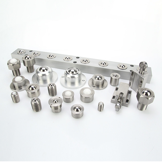
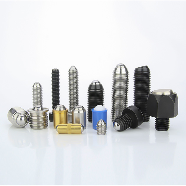
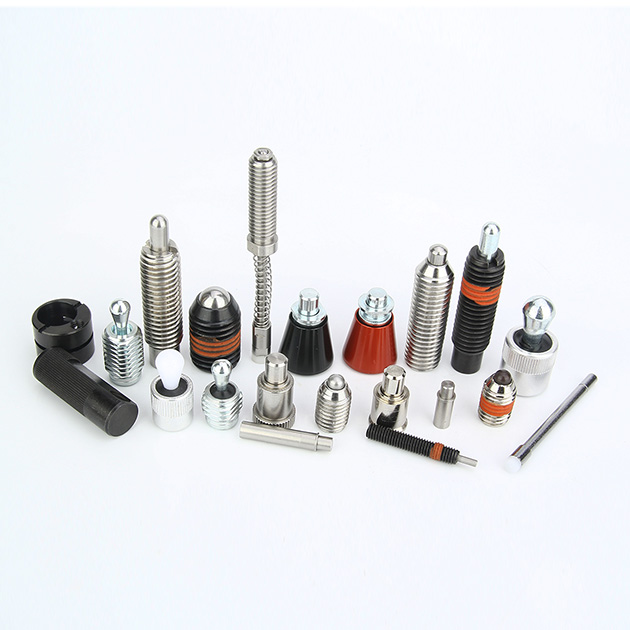
Selecting the correct nose geometry dictates the success of the application. Ball plungers feature a spherical rolling element. They are highly suitable for applications requiring side-load engagement and minimal friction. The rolling ball allows mating parts to slide over the plunger smoothly. They excel in sliding mechanisms, guiding parts, and shallow detent applications where the mating part needs to snap in and out of position easily.
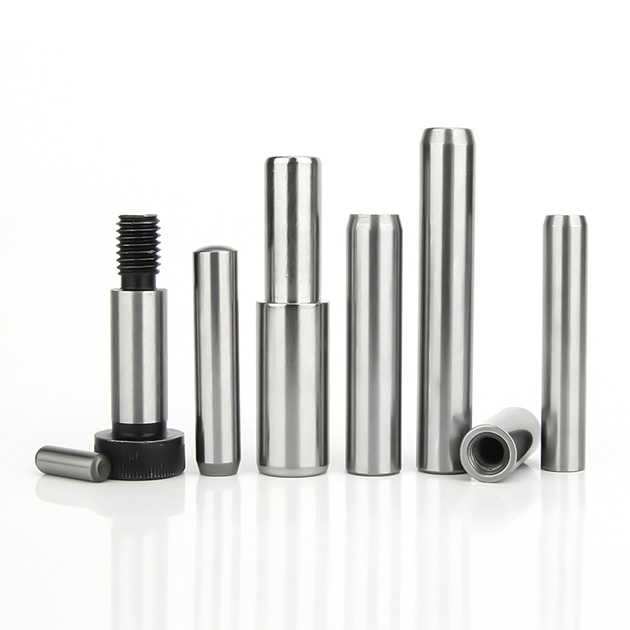
Pin plungers, often utilized as an industrial locating pin, feature a cylindrical nose. They offer a structural advantage for deeper engagement into mating holes. The cylindrical shape handles higher shear loads than a ball. Pin plungers provide precise alignment where a spherical ball would lack sufficient surface contact to hold a heavy part securely. When you need to lock a heavy fixture plate in place, a pin plunger is the only viable option.
Feature | Ball Plungers | Pin Plungers |
|---|---|---|
Contact Type | Rolling, point contact | Sliding, surface contact |
Engagement Depth | Shallow | Deep |
Shear Load Capacity | Low | High |
Primary Use Case | Detenting, guiding, sliding | Locating, ejecting, holding |
Friction Level | Minimal | Moderate to High |
Hand-Retractable vs. Fixed Plungers
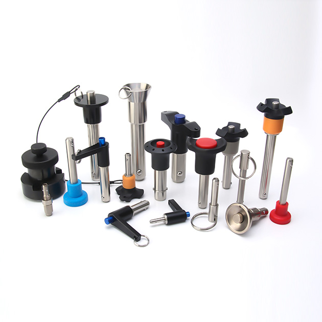
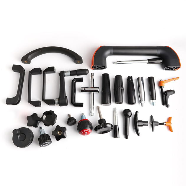
Hand-retractable plungers feature external actuation methods like pull-rings, L-handles, or T-handles. These designs are necessary in applications requiring frequent manual intervention. Operators use them on adjustable jigs, sliding rails, or quick-release fixtures. The handle allows the operator to retract the pin manually, move the fixture, and release the pin to lock it back into place. This eliminates the need for secondary hand tools like wrenches, speeding up the adjustment process.
Fixed plungers contrast sharply with retractable models. They feature standard internal drives, such as hex or slotted heads, and sit flush or sub-flush within the tooling. These are designed for set-and-forget automated operations. Once installed, they rely entirely on the mechanical force of the moving workpiece to compress the spring. You install them, set the depth, and let the machine do the work.
Threaded vs. Press-Fit Installation
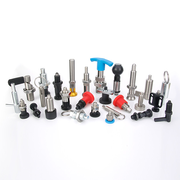
Threaded bodies provide significant advantages for fine-tuning engagement depth. Installers can turn the plunger in or out to adjust exactly how far the nose protrudes. This adjustability is highly beneficial for a high-wear assembly line plunger. When the nose eventually wears down from millions of cycles, maintenance teams can simply unscrew the old unit and thread in a replacement in seconds.
Press-fit or smooth body plungers serve different use cases. They are evaluated for scenarios where threading the host material is impractical or too costly. They excel where space is severely limited or when a completely flush mounting surface is required. Installers retain press-fit plungers using set screws, retaining rings, or industrial adhesives. You typically see these in high-density injection molds where tapping a thread is impossible due to cooling lines.
Material Selection and Environmental Compliance
Standard Steel vs. Stainless Steel Spring Plungers
Standard carbon steel plungers offer excellent tensile strength and cost-efficiency. They typically feature a black oxide finish to provide mild corrosion resistance. These are suitable for dry, indoor manufacturing environments where moisture is not a concern. If you are building a standard welding fixture or a dry assembly jig, carbon steel gets the job done reliably.
However, aggressive environments demand superior materials. A stainless steel spring plunger is mandatory when specific compliance triggers are met. Cleanrooms require stainless steel to prevent particulate shedding from rust. Food and beverage processing facilities mandate it to comply with strict sanitation standards. Medical device manufacturing and chemical washdown zones rely on stainless steel to withstand harsh cleaning agents and prevent contamination. Using carbon steel in these environments guarantees premature failure and audit violations.
Material Type | Corrosion Resistance | Tensile Strength | Best Application Environment |
|---|---|---|---|
Carbon Steel (Black Oxide) | Low | Very High | Dry indoor machining, standard assembly |
300 Series Stainless Steel | High | Moderate | Food processing, medical, cleanrooms |
400 Series Stainless Steel | Moderate | High | High-wear washdown environments |
Brass | Moderate | Low | Non-magnetic requirements, spark-free zones |
Nose Material: Metal vs. Polymer (Delrin/Nylon)
Workpiece marring is a serious defect in manufacturing. When a hard steel plunger strikes a soft workpiece, it leaves dents and scratches. To mitigate this risk, you must specify Delrin or nylon noses. These polymer tips protect soft metals like aluminum, brass, and copper. They also prevent scratching on finished plastic components or painted surfaces. A polymer nose absorbs the impact without transferring the damage to the part.
In contrast, hardened steel or stainless steel noses are required for high-cycle, abrasive environments. Heavy cast iron parts or rough-machined steel will rapidly degrade a polymer tip. Metal noses withstand the repeated impact and friction of heavy industrial automation without losing their dimensional accuracy. If you are locating raw castings, always use a hardened steel nose.
Spring Material and Fatigue Life
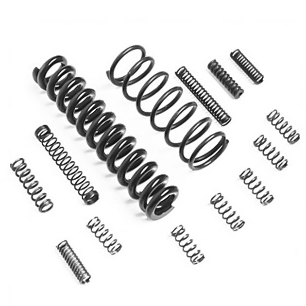
The internal mechanics of a plunger rely heavily on the spring material. Standard applications use high-carbon music wire springs. Music wire offers excellent fatigue life under normal operating temperatures. Stainless steel springs are utilized when corrosion resistance is needed inside the plunger body, preventing the spring from rusting and snapping.
Extreme temperatures alter spring rates significantly. High heat environments, like plastic injection molding, or cryogenic applications dictate the necessity of specialized spring alloys. Materials like Inconel or specialized stainless grades prevent premature spring fatigue. Using standard music wire in a high-heat application causes the spring to lose its temper, resulting in immediate failure and a dead plunger.
Engineering Trade-Offs and Implementation Risks
Stroke Length vs. Spring Force
Designing fixtures in confined spaces requires managing the inverse relationship between stroke length and spring force. Achieving a longer stroke often requires a longer, softer spring. This sacrifices the maximum holding force. Conversely, a short, stiff spring provides high force but limits the travel distance of the nose. You cannot have maximum stroke and maximum force in a micro-plunger.
You must calculate the required initial pre-load and final spring forces. The initial force must be high enough to hold the part steady the moment it makes contact. The final force, when fully compressed, must not exceed the structural limits of the workpiece or the plunger itself. Proper calculation ensures the plunger neither bottoms out prematurely nor fails to hold the component securely during machining.
Determine the weight and mass of the workpiece being held.
Calculate the static friction coefficient of the fixture surface.
Identify the dynamic forces introduced by cutting tools or conveyor movement.
Select a spring rate that overcomes these forces without deforming the part.
Verify the compressed length of the spring to ensure it does not bottom out solid.
Managing Side Loads and Shear Forces
Standard pin plungers possess mechanical limitations when subjected to lateral forces. A heavy side load can bend the pin, bind the internal spring, or shear the nose off entirely. Plungers are primarily designed to handle axial, straight-line compression. Hitting a standard pin plunger from the side repeatedly will destroy it.
Mitigation strategies are required when side loads are unavoidable. You should select lateral plungers specifically engineered for horizontal forces. Alternatively, redesign the mating receptacle. Adding a chamfer or lead-in angle to the mating hole reduces the sudden shear stress on the plunger nose as the part slides into position. This simple machining step extends the life of the plunger tenfold.
Installation Torque and Vibration Loosening
High-vibration industrial machinery presents a constant risk of threaded components backing out. A loose plunger alters the positioning coordinates, leading to rejected parts or catastrophic tool crashes. Proper installation torque is necessary, but often insufficient on its own when dealing with heavy stamping presses or high-speed milling machines.
You must evaluate several mitigation tactics to secure the installation. Utilizing liquid threadlockers during assembly provides a strong chemical bond. Specifying plungers with pre-applied nylon locking patches offers a mechanical prevailing torque that resists vibration immediately upon installation. In through-hole applications, using a jam nut on the back of the plunger physically locks the installation depth in place, guaranteeing it will not move.
Conclusion
Spring plungers are highly engineered components that directly impact machine reliability, tooling changeover speed, and product quality. Treating them as afterthoughts during the design phase leads to inconsistent manufacturing outcomes and increased maintenance downtime. Selecting the precise combination of nose geometry, spring force, and material ensures long-term operational success on the shop floor.
To implement these solutions effectively, execute the following steps:
Download manufacturer CAD models to perform accurate interference checking within your assembly files before cutting metal.
Request physical samples to conduct real-world cycle testing under actual operating conditions.
Consult with manufacturer engineering support to customize spring force requirements for unique applications.
Audit your current tooling setups to identify areas where manual clamping can be replaced by automated plungers.
FAQ
Q: What is the difference between a ball plunger and a standard spring plunger?
A: The primary difference lies in the nose type. Ball plungers utilize a rolling spherical ball, making them ideal for sliding, guiding, and shallow detent applications where minimal friction is required. Standard spring plungers use a cylindrical pin, providing an extended stroke and deeper engagement for precise locating, part ejection, and handling higher shear loads.
Q: How do you calculate the required spring force for a positioning plunger?
A: Calculating required spring force involves accounting for the weight of the part being held, the friction coefficients of the sliding surfaces, and the dynamic forces generated by the moving assembly line. The initial pre-load force must overcome static friction, while the final force must hold the part securely without causing deformation.
Q: When is it necessary to specify a stainless steel spring plunger?
A: You must specify stainless steel in environments where standard carbon steel would corrode or seize. This includes chemical washdown zones, food and beverage processing facilities, cleanrooms, high-humidity areas, and applications exposed to extreme temperatures or harsh industrial solvents.
Q: When should I use a hand-retractable spring plunger?
A: Hand-retractable models are recommended for applications requiring frequent manual adjustments. They are essential for quick-change tooling, adjustable fixture plates, and manual locking mechanisms where operators need to make rapid, secure adjustments without relying on secondary hand tools like wrenches.
Q: Can spring loaded plungers handle side loads?
A: Standard pin plungers are generally weak against heavy side loads and can bend or bind. However, specific lateral plungers and ball plungers are explicitly designed to accommodate horizontal forces. If side loads are present, you must select a plunger engineered for lateral pressure or modify the mating receptacle.
Q: What is the typical cycle life of an industrial locating pin?
A: The cycle life typically ranges from hundreds of thousands to several million cycles. Longevity depends heavily on the internal spring material, the operating environment, and strict adherence to maximum stroke limits to prevent spring fatigue and bottoming out.
Q: How do you prevent an assembly line plunger from backing out due to vibration?
A: To prevent backing out in high-vibration environments, recommend using plungers with integrated nylon locking elements. Alternatively, apply liquid thread-locking compounds during installation, or use mechanical jam nuts to secure the plunger firmly against the tooling fixture.


